ghodges
-
Posts
8,126 -
Joined
-
Last visited
-
Days Won
363


Recent Profile Visitors
9,667 profile views


-
The word that comes to mind is WOW! Gil
-
Advice from someone as experienced as yourself is always noted and appreciated! I considered gloss coating the kit sheet, but after the very first decal (the nose stripe) went on without any problems, I decided not to. Even if I had, I'd have never considered using the Micro Scale decal film instead, so I'll have to give that a go in the future if needed. Thanks! Gil
-
As much work as it is, I'm sure getting those attached feels like a good step forward! Gil
-
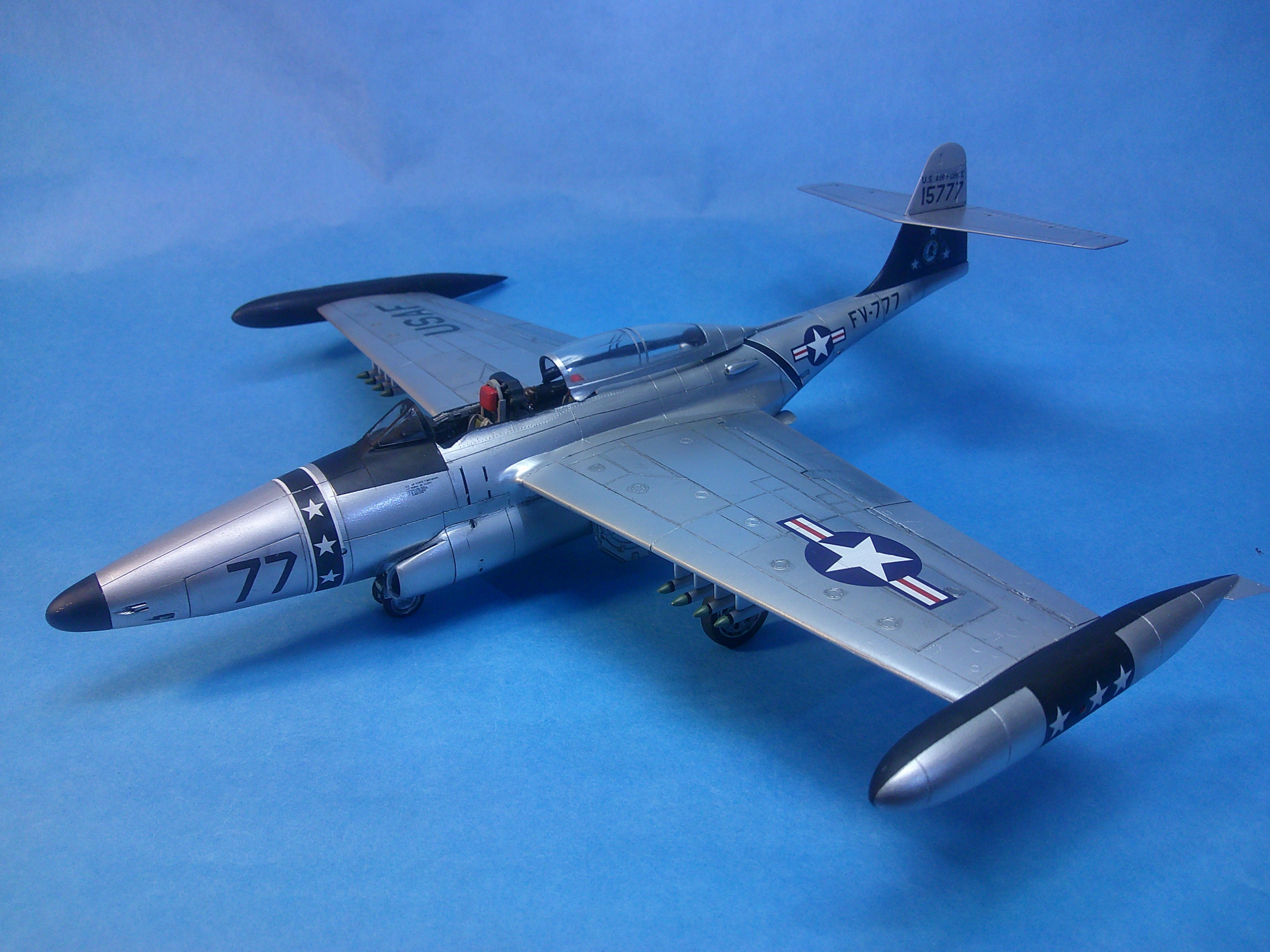
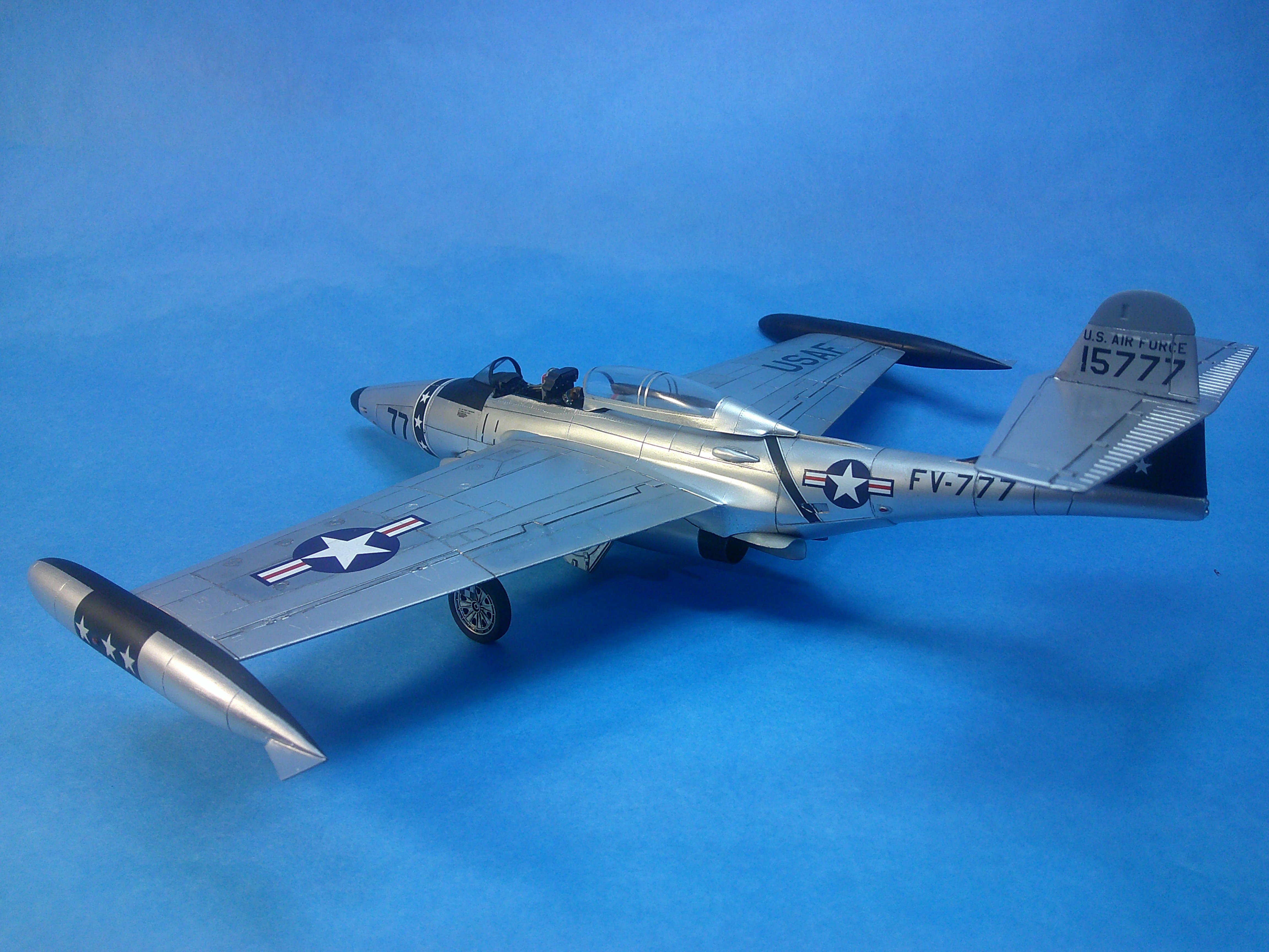
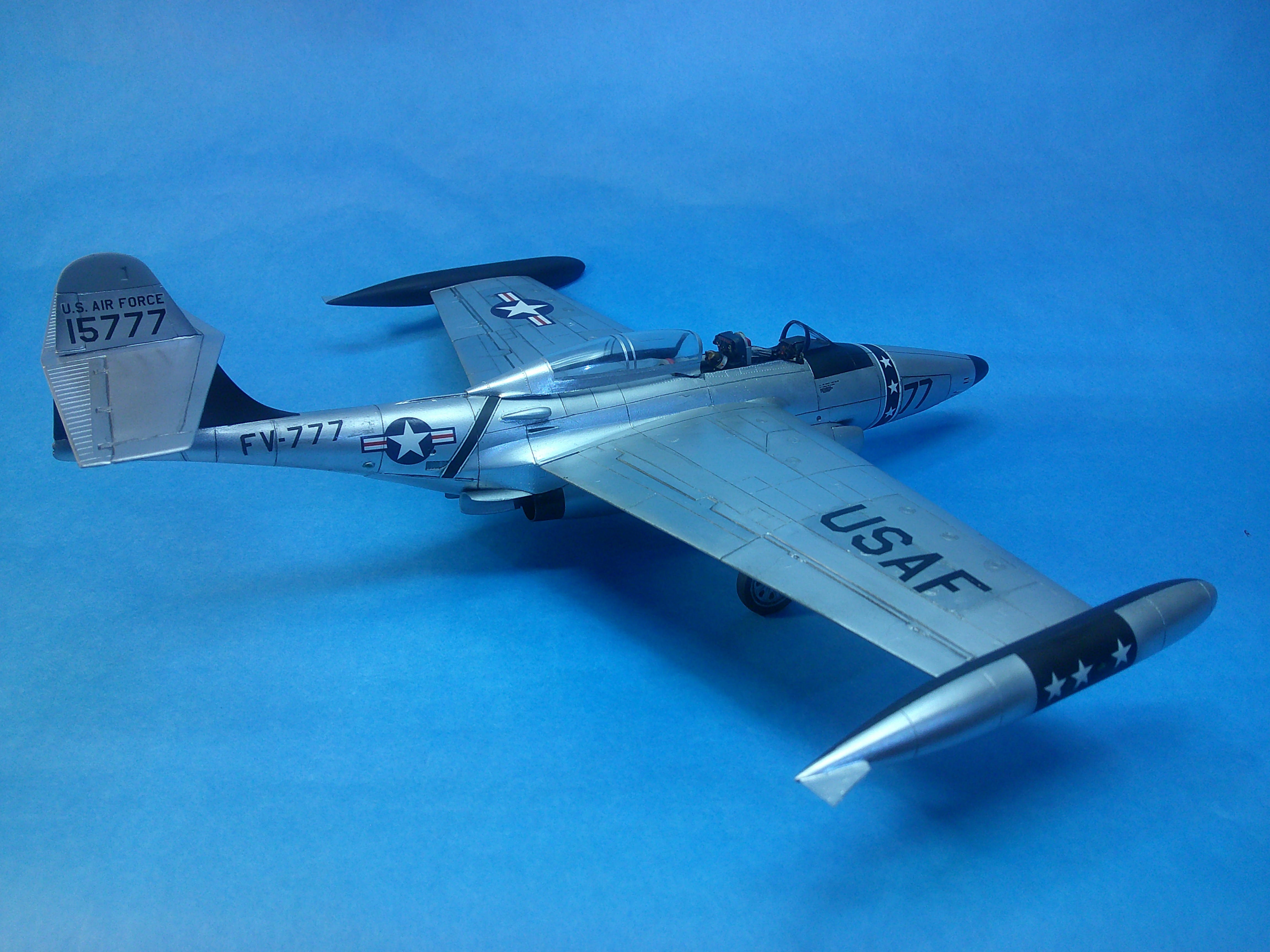
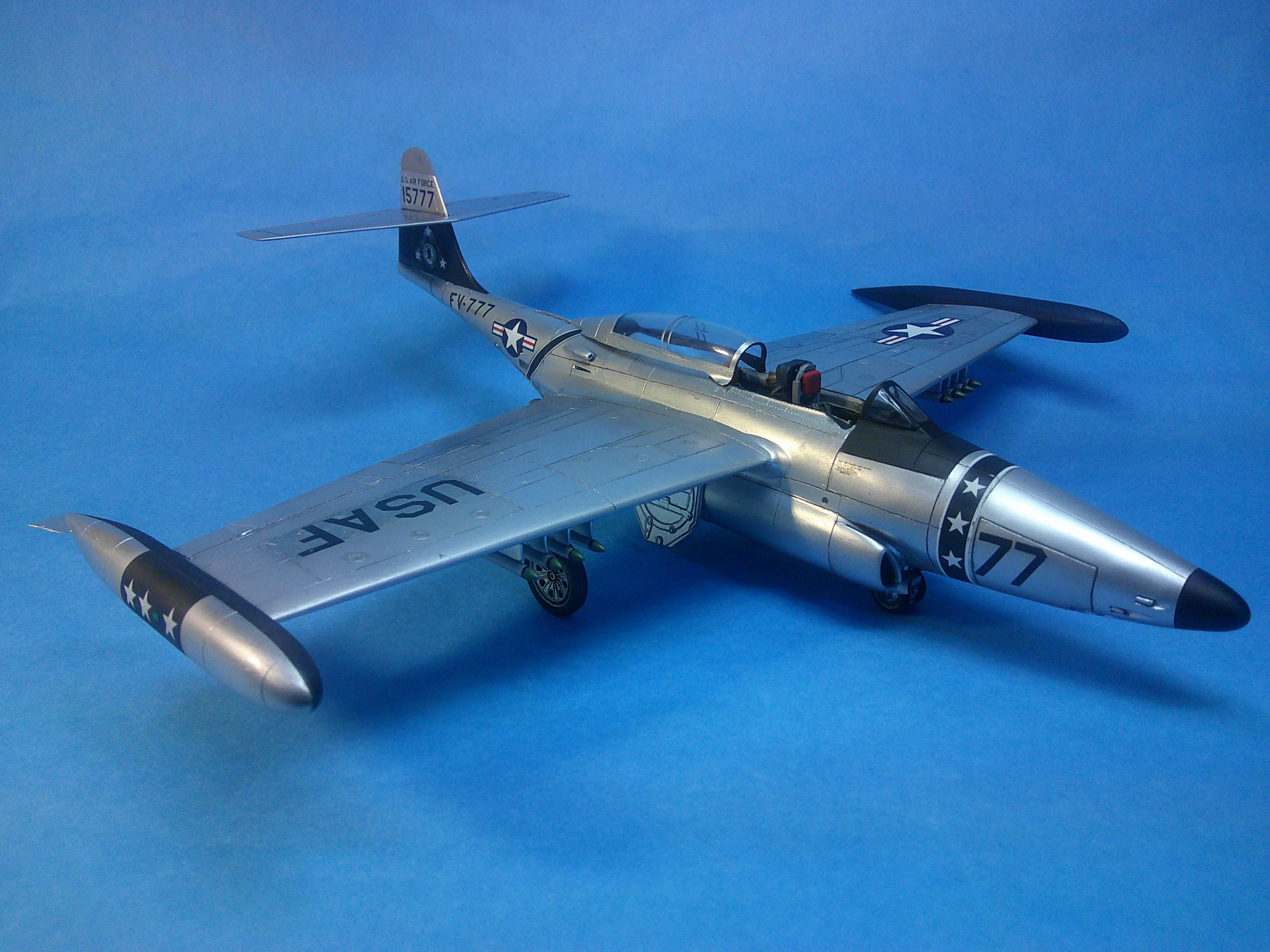
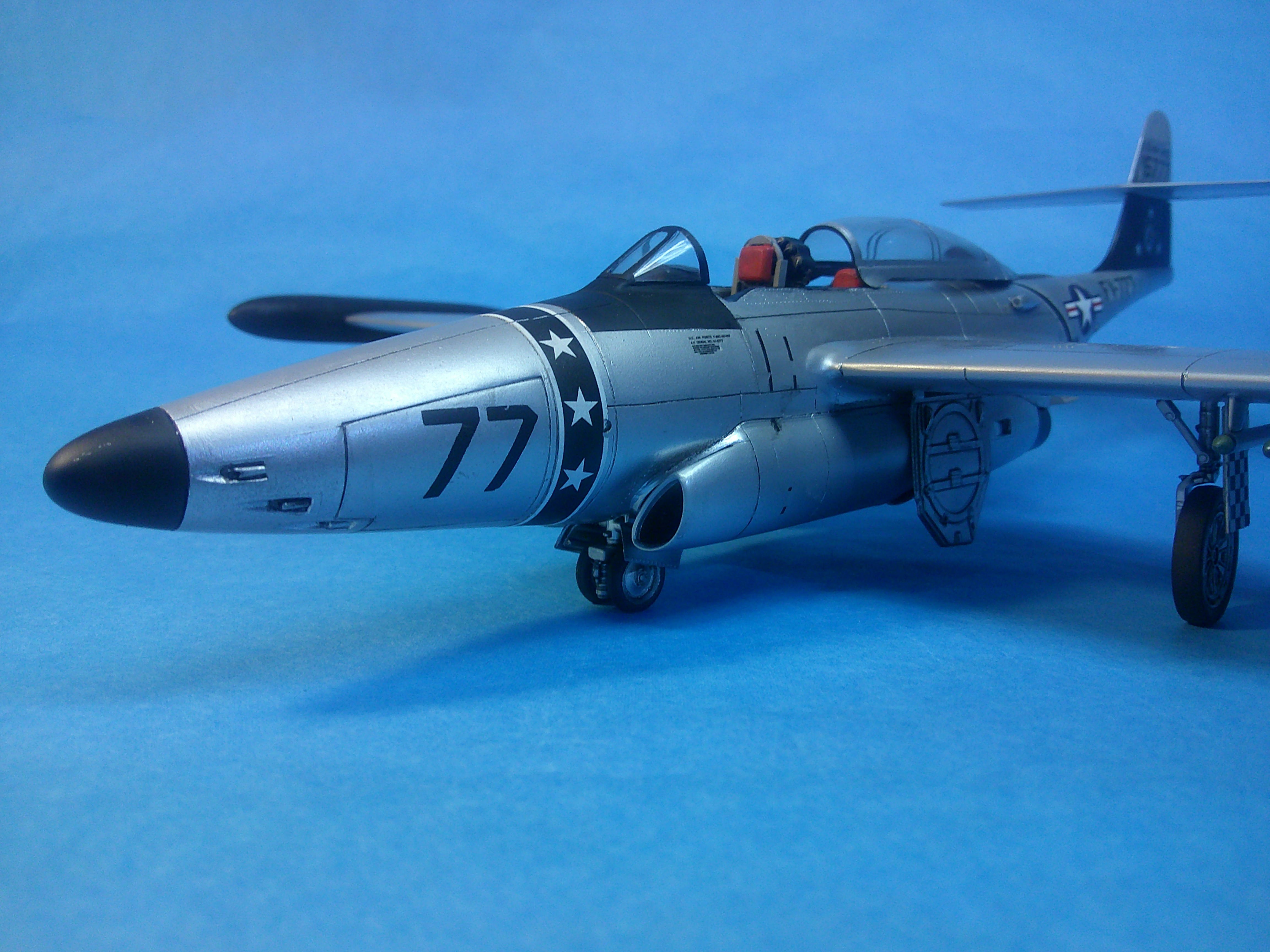
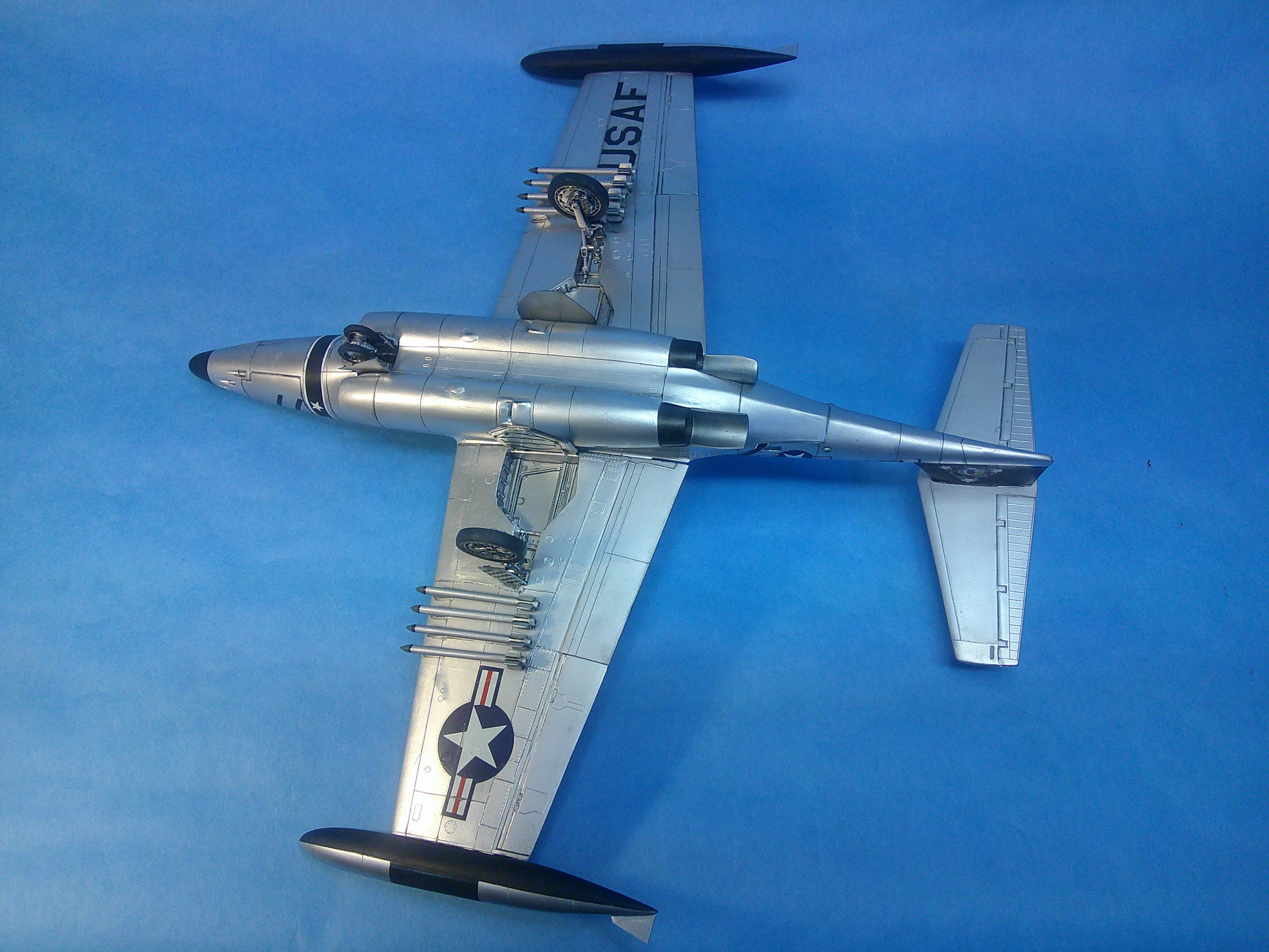
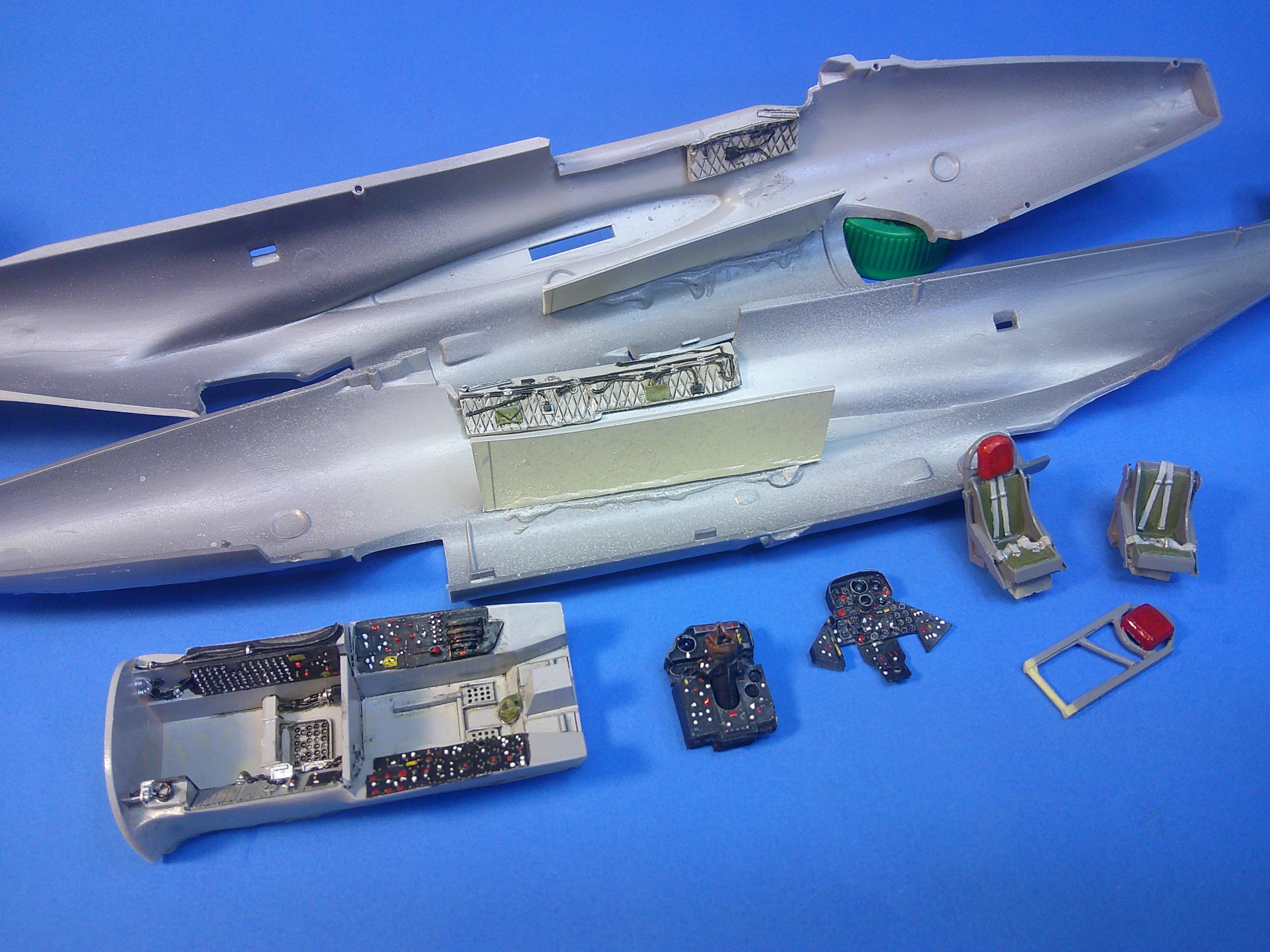
This is the 1/48 Revell(ogram) F-89C Scorpion. It's a relatively simple and straight forward kit with very good detail inside and out giving you very good "bang for your buck". I opted to add a Black Box resin interior which only needs the addition of some plastic to act as floor supports and the removal of the molded-in interior side fuselage cockpit detailing in order to fit the resin side panels in place. The kit interior is actually quite good though the rein seats with their harnesses molded in are a real step up from the kit seats. The rest of the build is OOTB except for the addition of sheet plastic wing tank fins that were commonly added to the plane later in its life. This kit does come with raised panel line detailing so I did rescribe 90% of the lines on the kit using a razor saw. I used Tamiya TS-30 Silver leaf as the overall NMF sprayed over an undercoat of Gloss Black. I then masked some areas and used both Alclad and AK Metallics for the varying panels on the model as well as Steel, Titanium, and Jet exhaust for the exhaust area. These are the kit markings and they gave me fits, tending to curl up at the edges badly. No amount of solvent would make them lie down, not even my strongest stuff so I resorted to "painting/plastering" some of them in place with some Future, which sucked them down in place when dry. I actually had to paint the black background for the tip tank stars as the black decals just wouldn't lie down and the edges frayed while trying to press them in place repeatedly. I also had to replace the nose numbers with black dry transfer rub on decals and use stars/bars and USAF decals from the spares box.. Except for the decaling phase, this was an easy build that took just 9 days. Now on to the next! Gil

-
Excellent tarp! Glue soaked tissue paper??? Gil
-
I'm amazed at all of the little details that keep being added! It's become much more involved than I imagined at the start! Gil
-
Nice build Ron! Also interesting to see inner strut braces not unlike those used on the Martin T4M! Gil
-
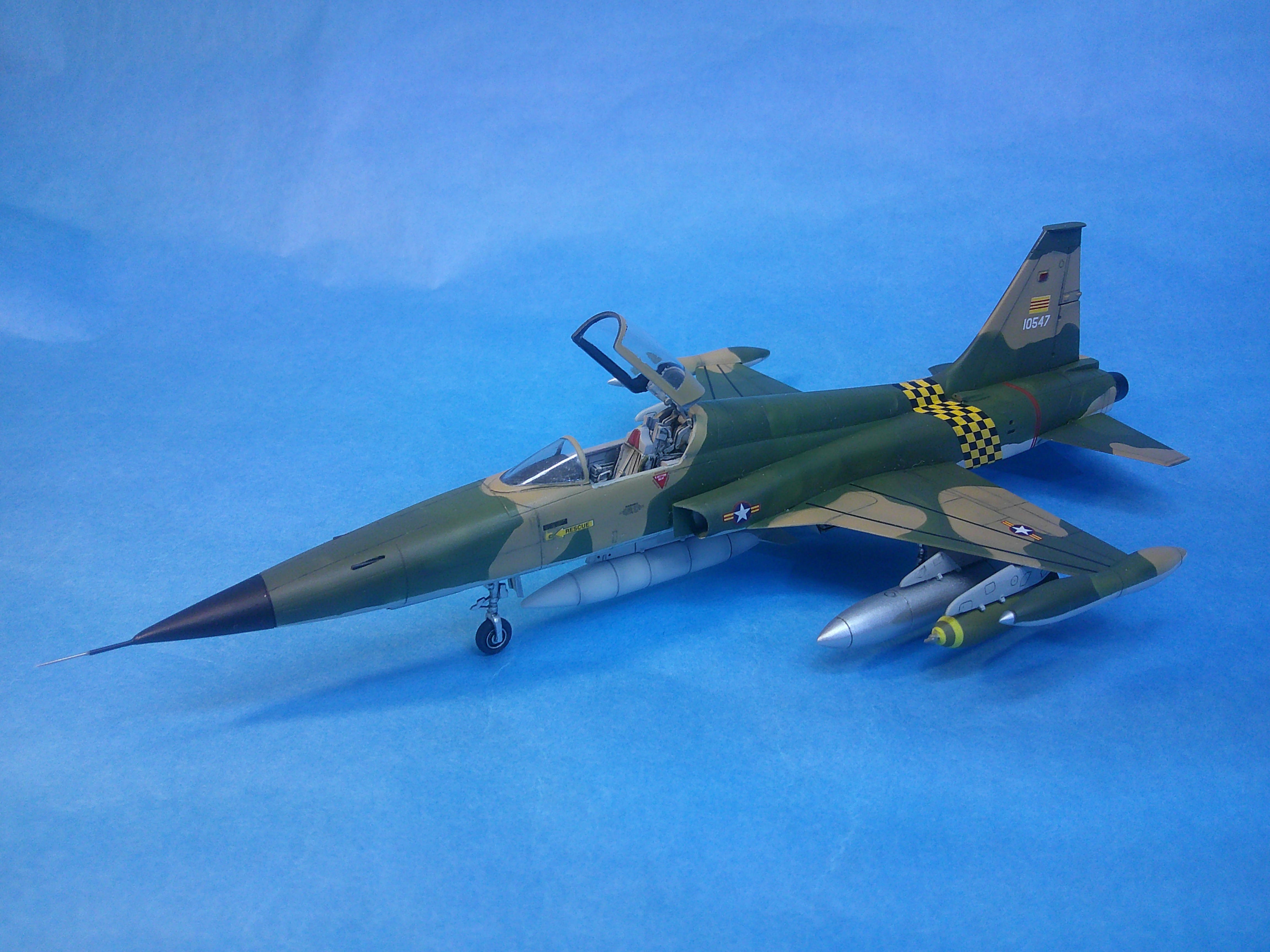
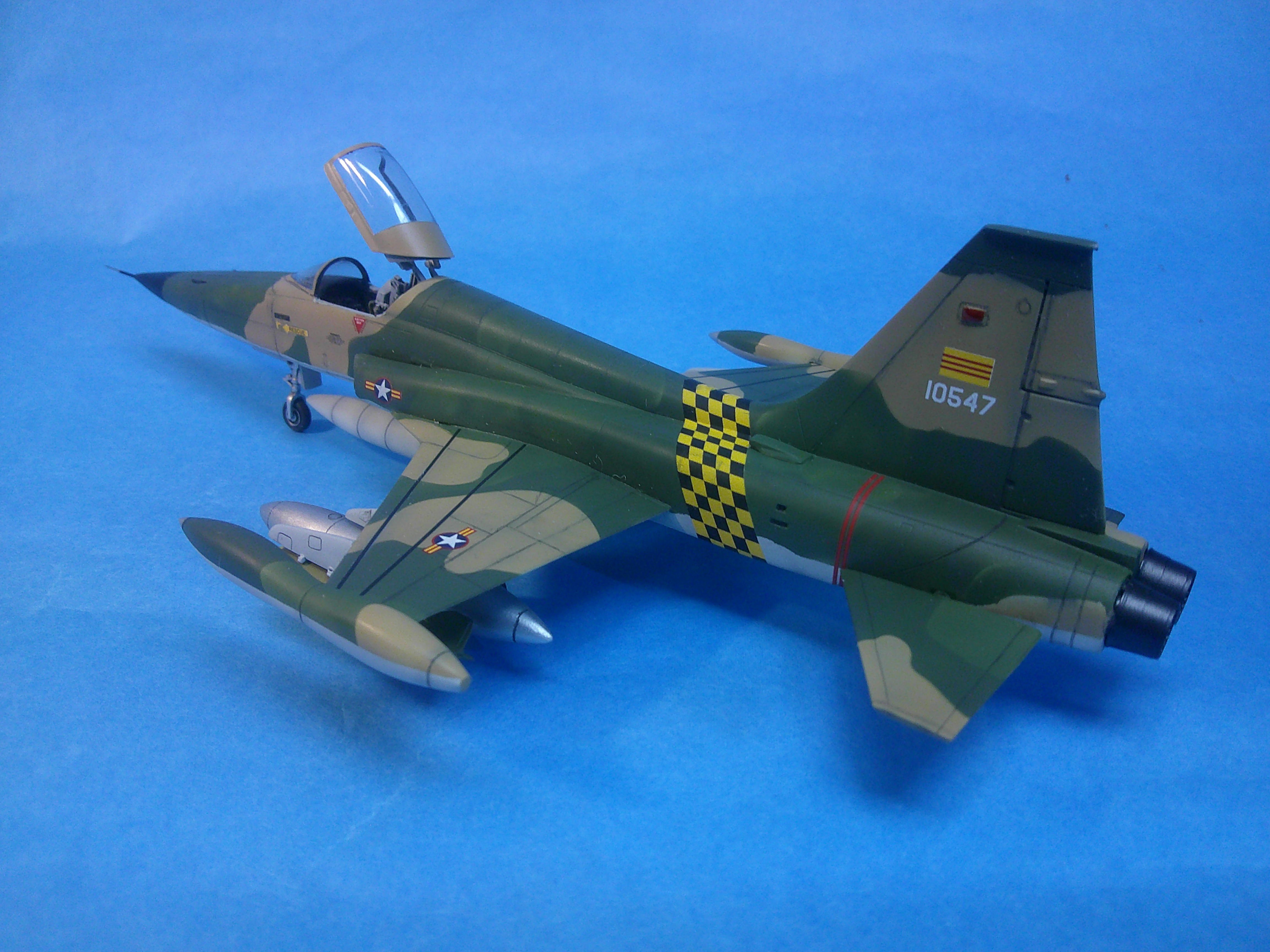
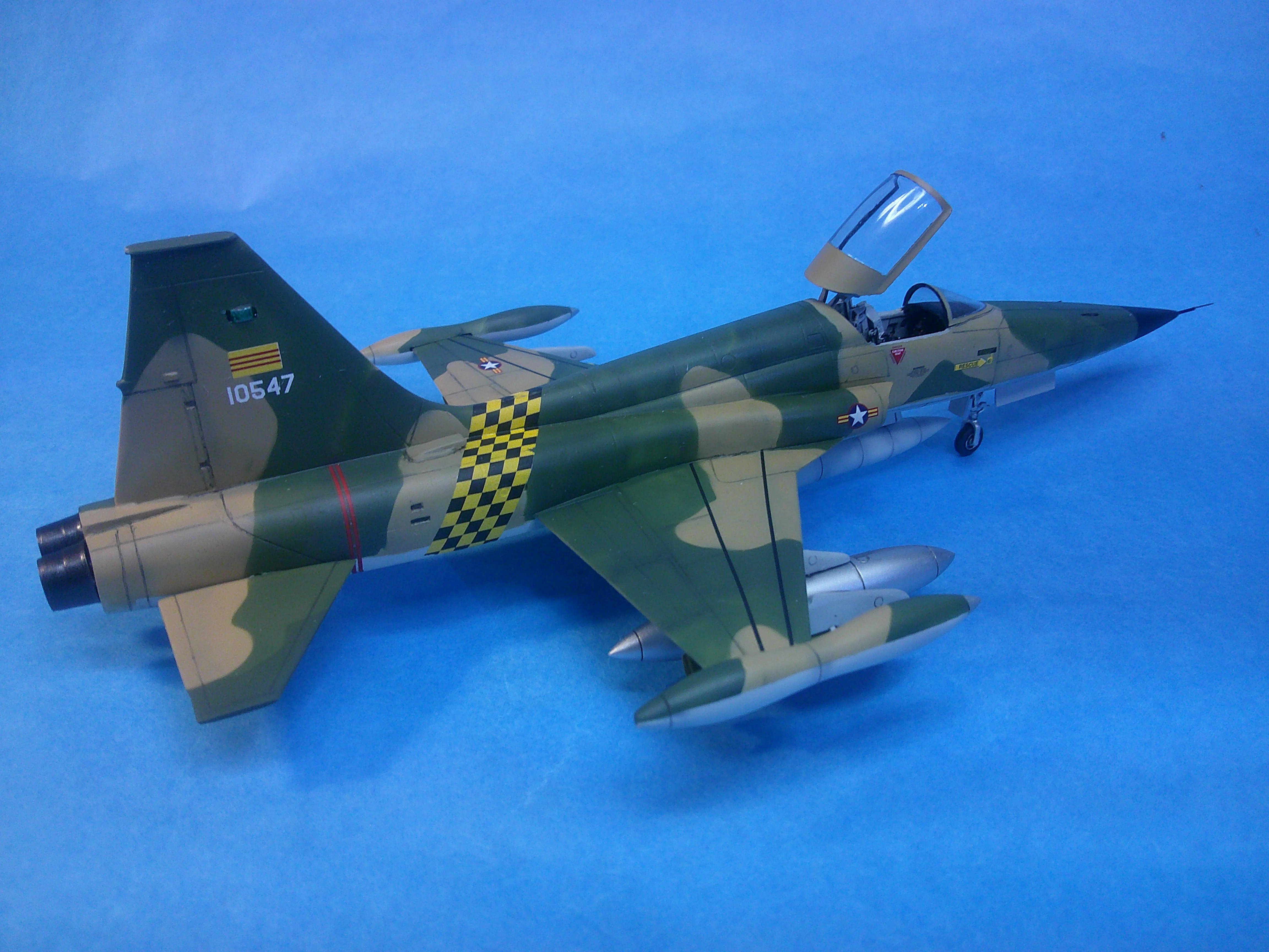
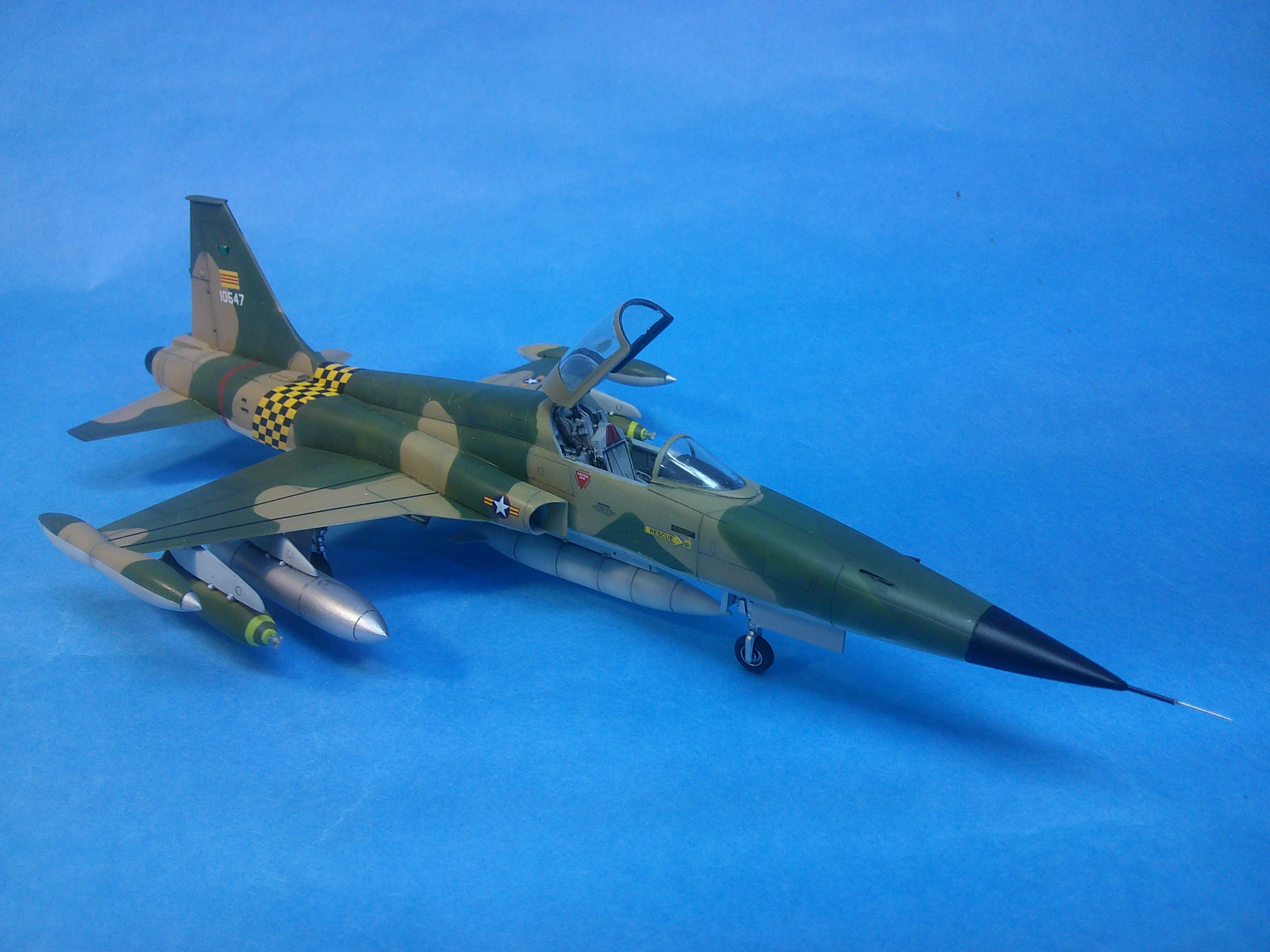
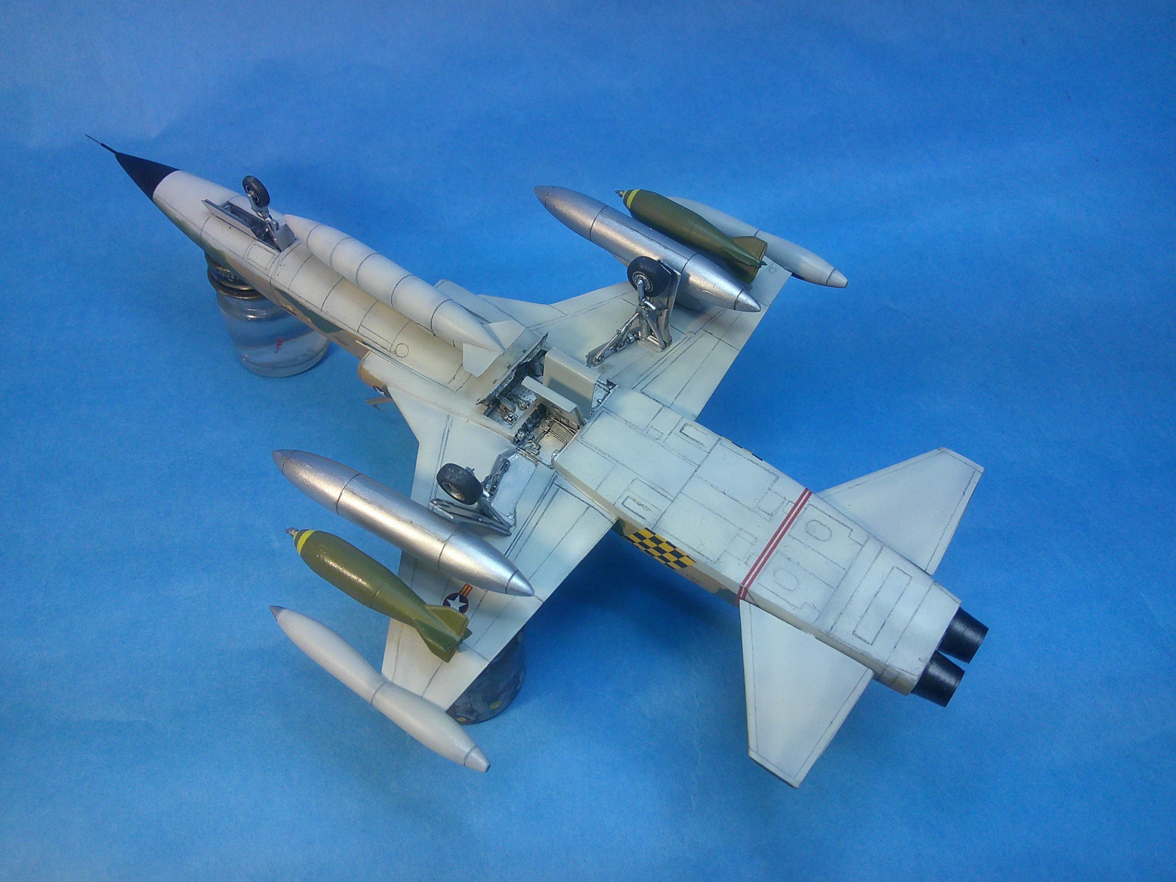
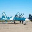
After taking almost 4 months on my last build I thought I'd "whip one out" to get back in the groove. Since our current club build theme is any kit manufactured after 1990, I grabbed this 2006 issued Classic Airframes 1/48 F-5A Freedom Fighter from the stash and built it OOTB in 11 days. This is a good kit, but NOT a Tamigawavellogram shake-n-bake type of build. The model has a very nicely appointed resin interior, but is short on locating pins and the fit has to be tweaked to get the best results. Both of the tail planes and all of the pylons, drop tanks, ordnance, and even the tires had to be drilled and pinned for security. The very thin wing made drilling the holes in the underside a real adventure when trying to go as deep as possible without drilling all the way through! I used True Color lacquer/enamel paints for the Vietnam era SEA paint scheme, masking it off using Silly Putty ropes at the edges of the patterns and tape to fill in the rest. I found the colors to be good, but looking at it now I'd go back and either slightly lighten the Medium Green or add a little black to darken the Dark Green to get slightly more contrast. I did some (but not all) of the panel lines in pencil where they could be easily seen on the lighter camo colors. I used the kit decals which generally went on with very few problems. All in all this was a fun little build that went smoothly even if it required a bit more re-engineering than a lot of other kits. It's was also good to get one done and on the shelf so quickly. Critiques, comments, and questions welcome as always! Cheers! Gil
-
May the Lord bless his family and friends with a multitude of loving and happy memories to buoy them through their time and sense of loss. Gil
-
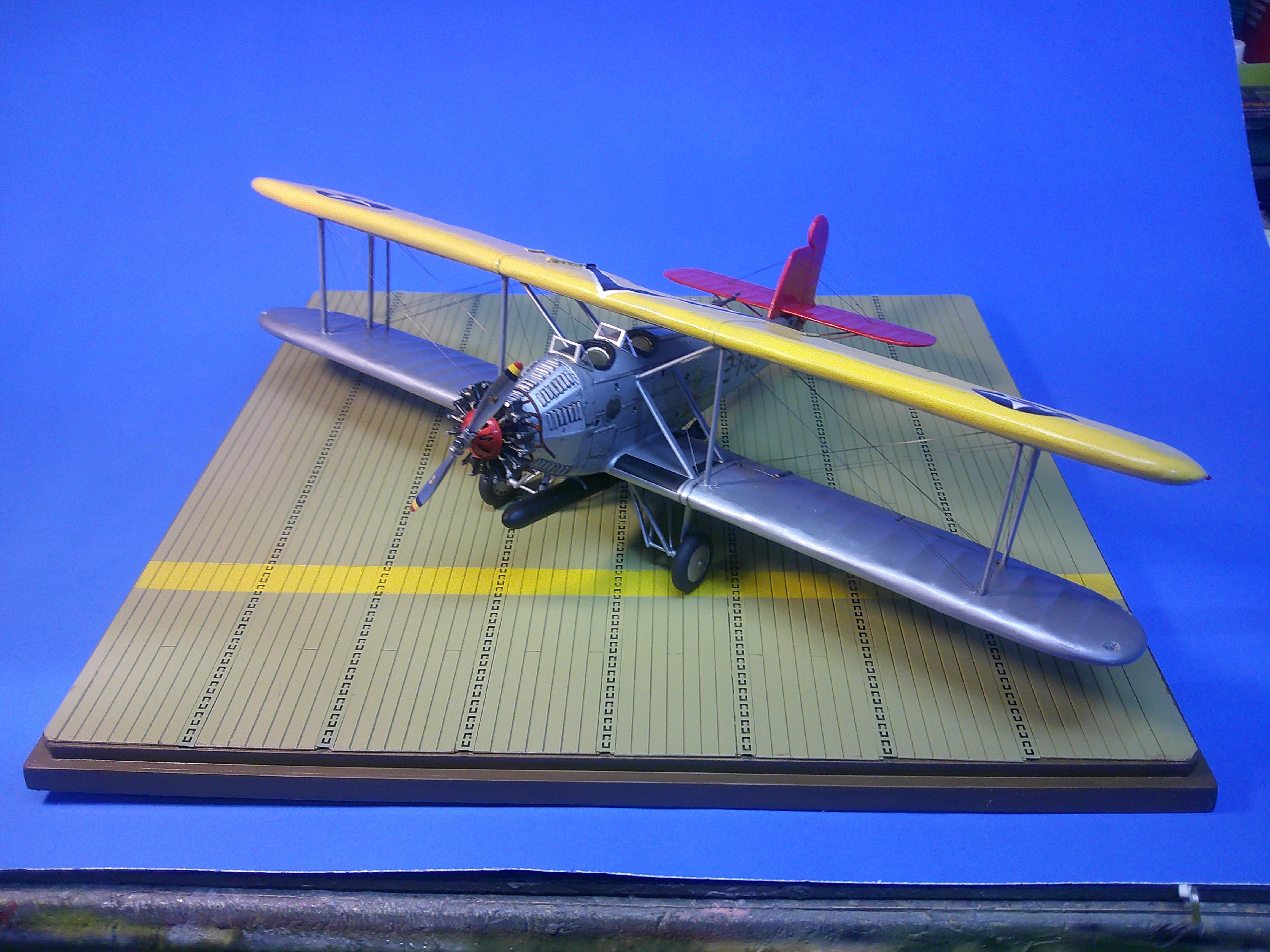
Thanks to everyone for the very kind words! I decided my torpedo bomber needed a display base. The base is a cast resin piece by Aircraft Carrier Products. It's some type of very light resin compared to most. The deck planks are cast in with spaces for PE tie down strips to be inserted. The PE tie down strips fit very well with only some end trimming needed to lop off a little excess length. The base was assembled and then sprayed with Tamiya Deck Tan. That was then masked in order to spray the yellow stripe that was typical of one side of the decks of the carriers Lexington and Saratoga @1930. The edges of the base were hand painted with dark brown to finish it. By the way, the PE strips didn't like being masked over so after the yellow was painted I had to go back and hand paint each tie down strip with deck brown where the tape had pulled the paint off. Eventually I'll create a label for the base to finish it off. Anyway, it does seem to make it a more "complete" display! Gil
-
Interesting glider! The design looks very old, but it also looks like it uses PVC piping for the struts. Or was it something round and light bamboo maybe? Gil
-
3 more winners Duke! Your modeling always amazes me both in the numbers you crank out and the W-I-D-E variety of subjects you choose. Since it took me 3-1/2mos to finish just my ONE latest project, I especially feel like a slug by comparison. Looking forward to you next batch from the hangar! Gil
-
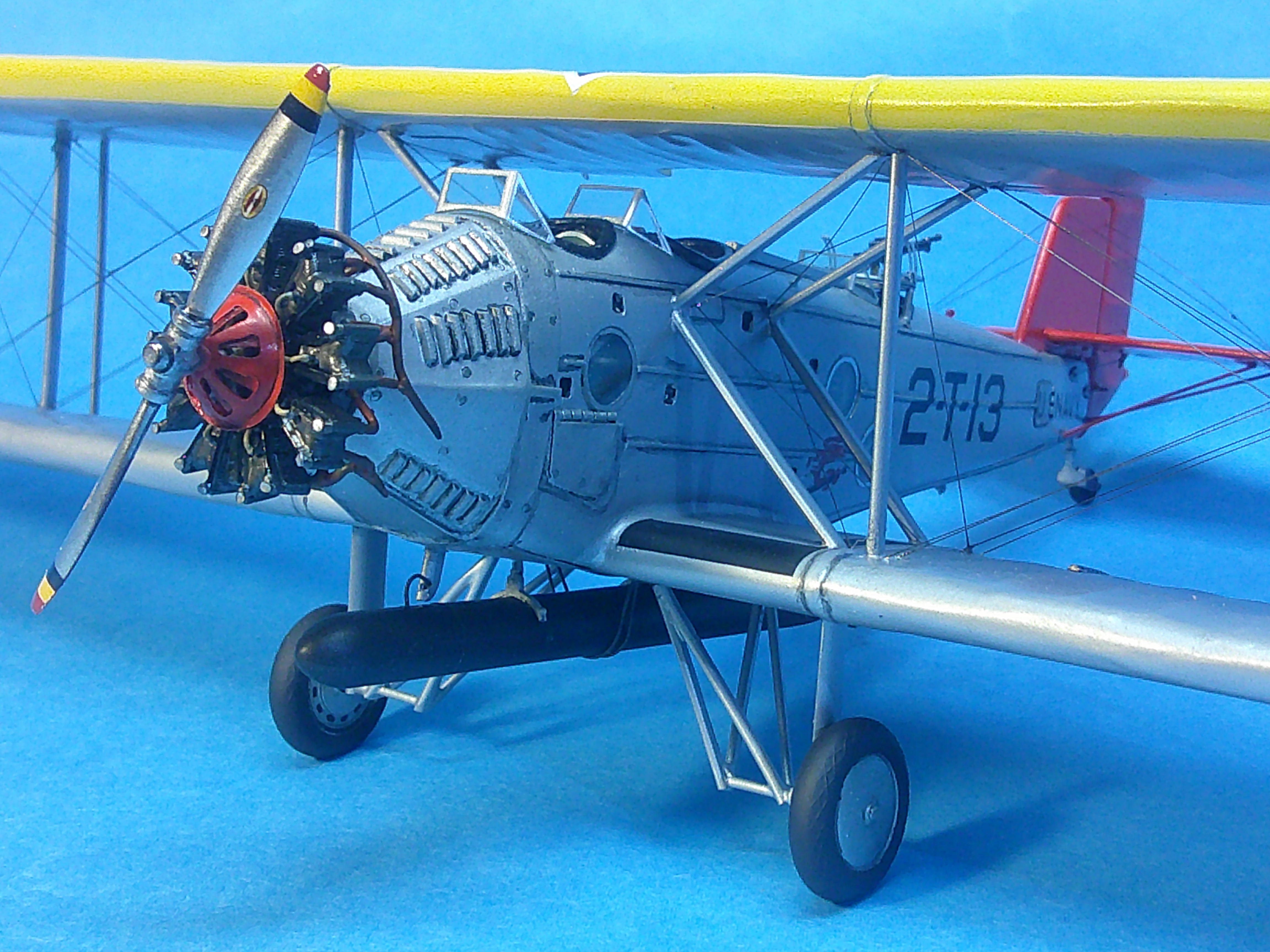
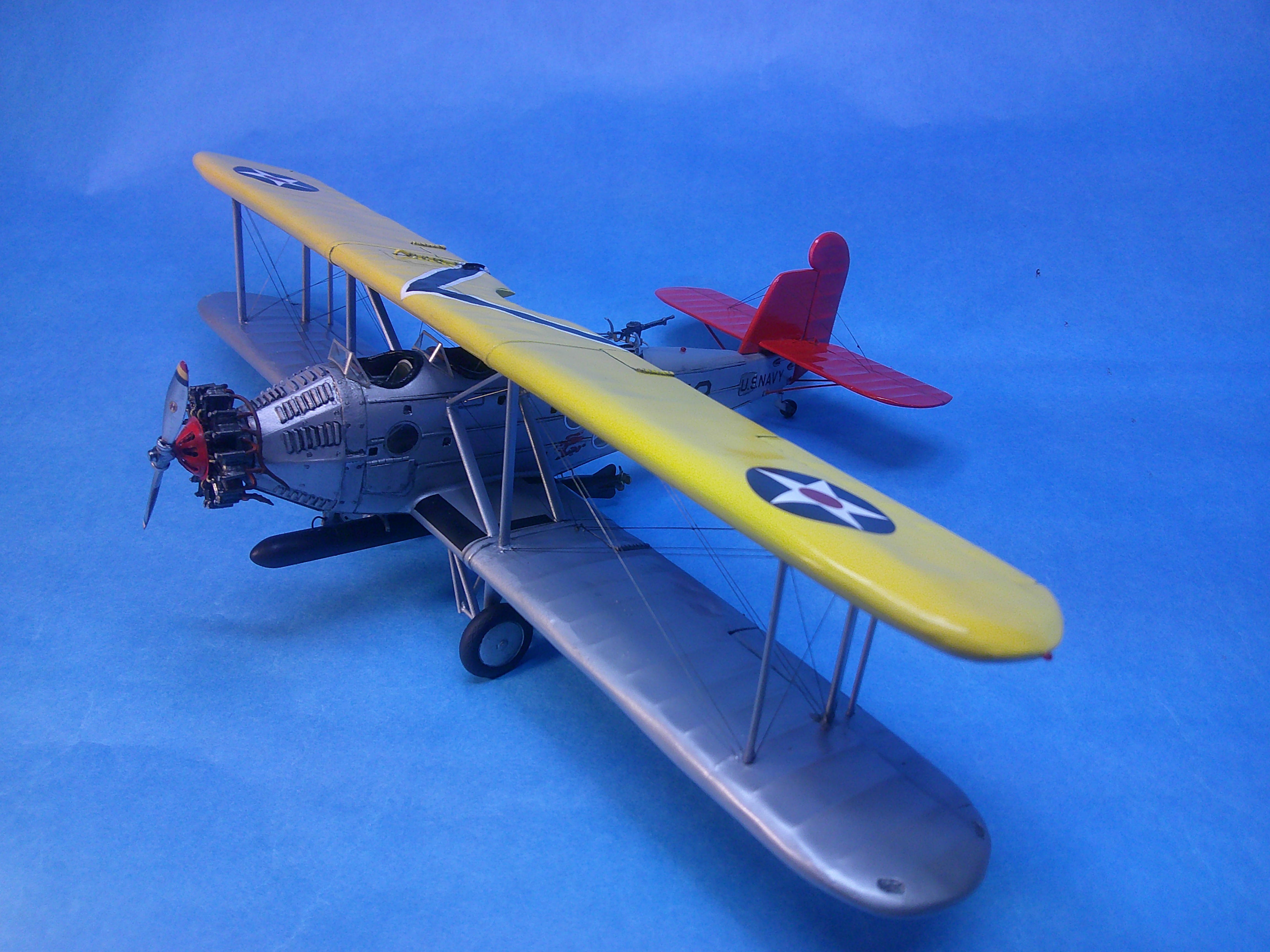
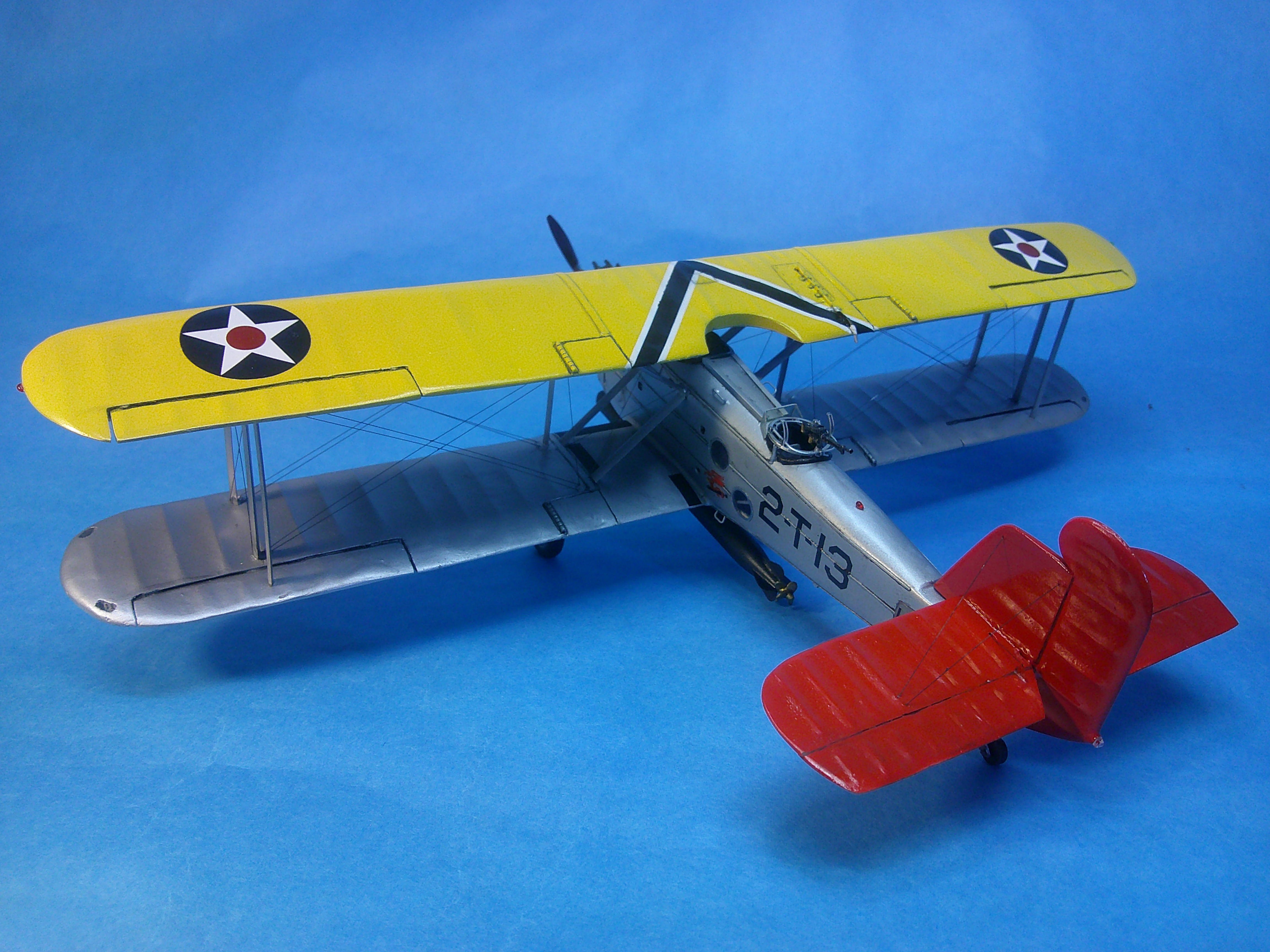
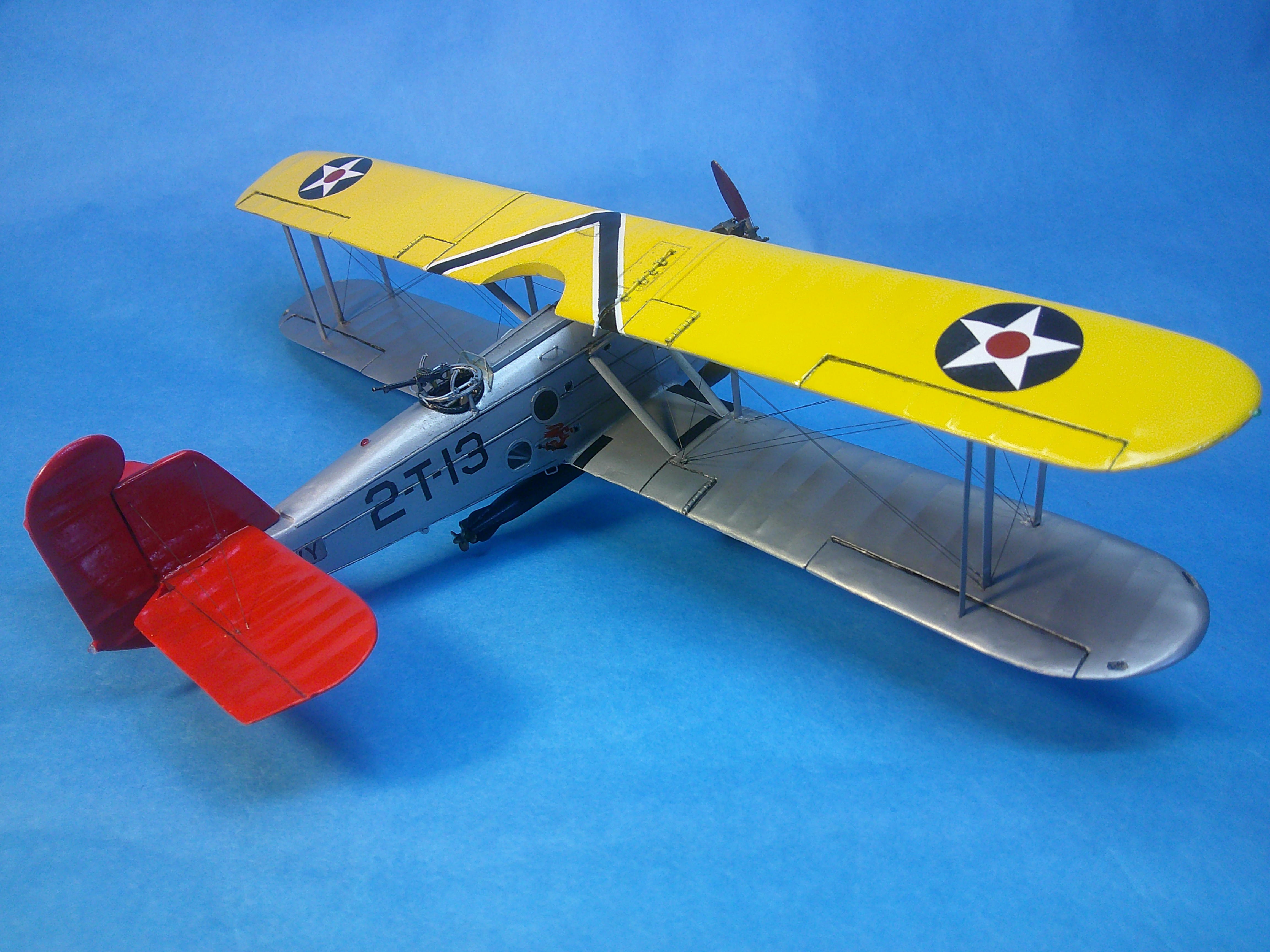
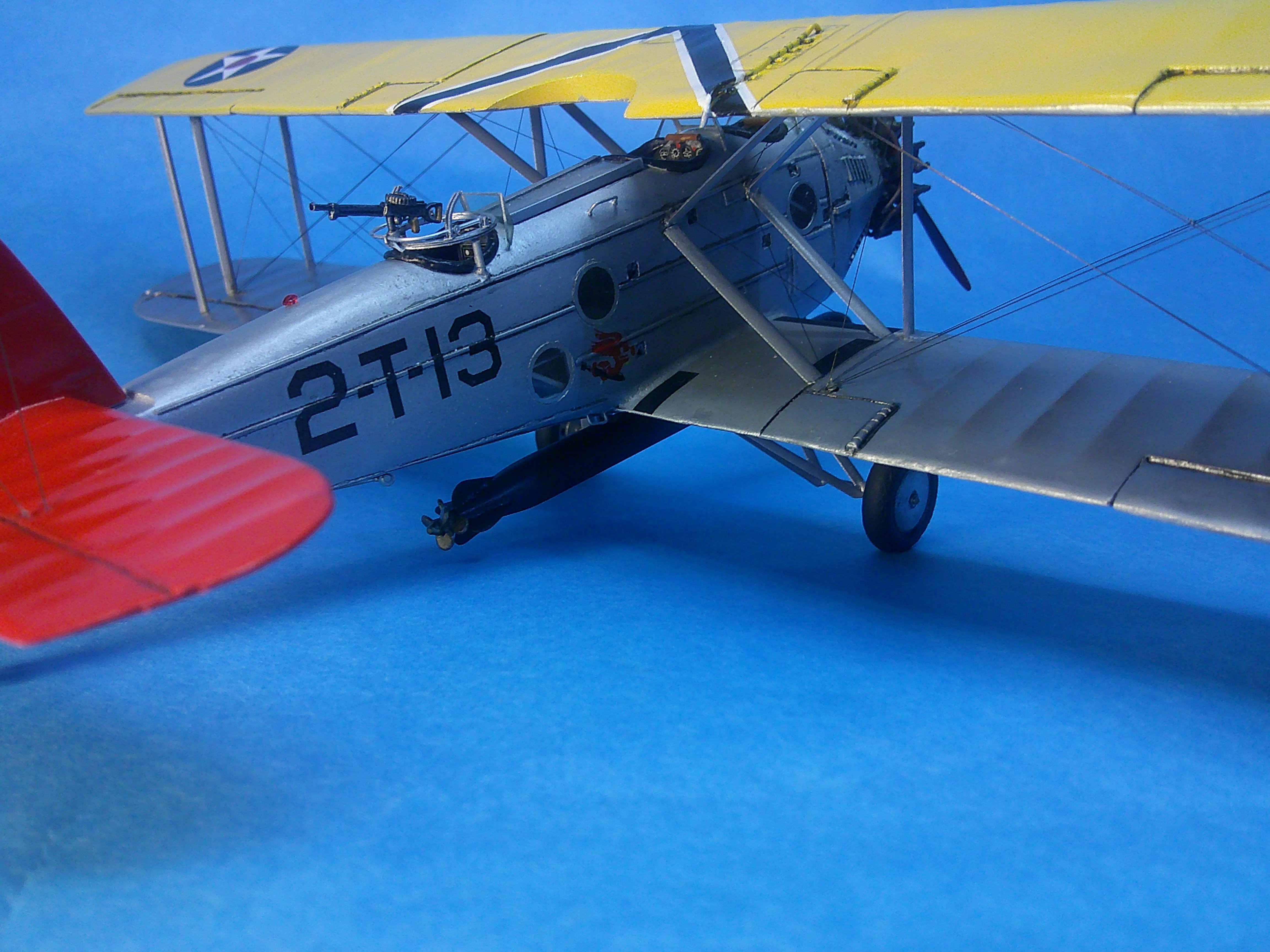
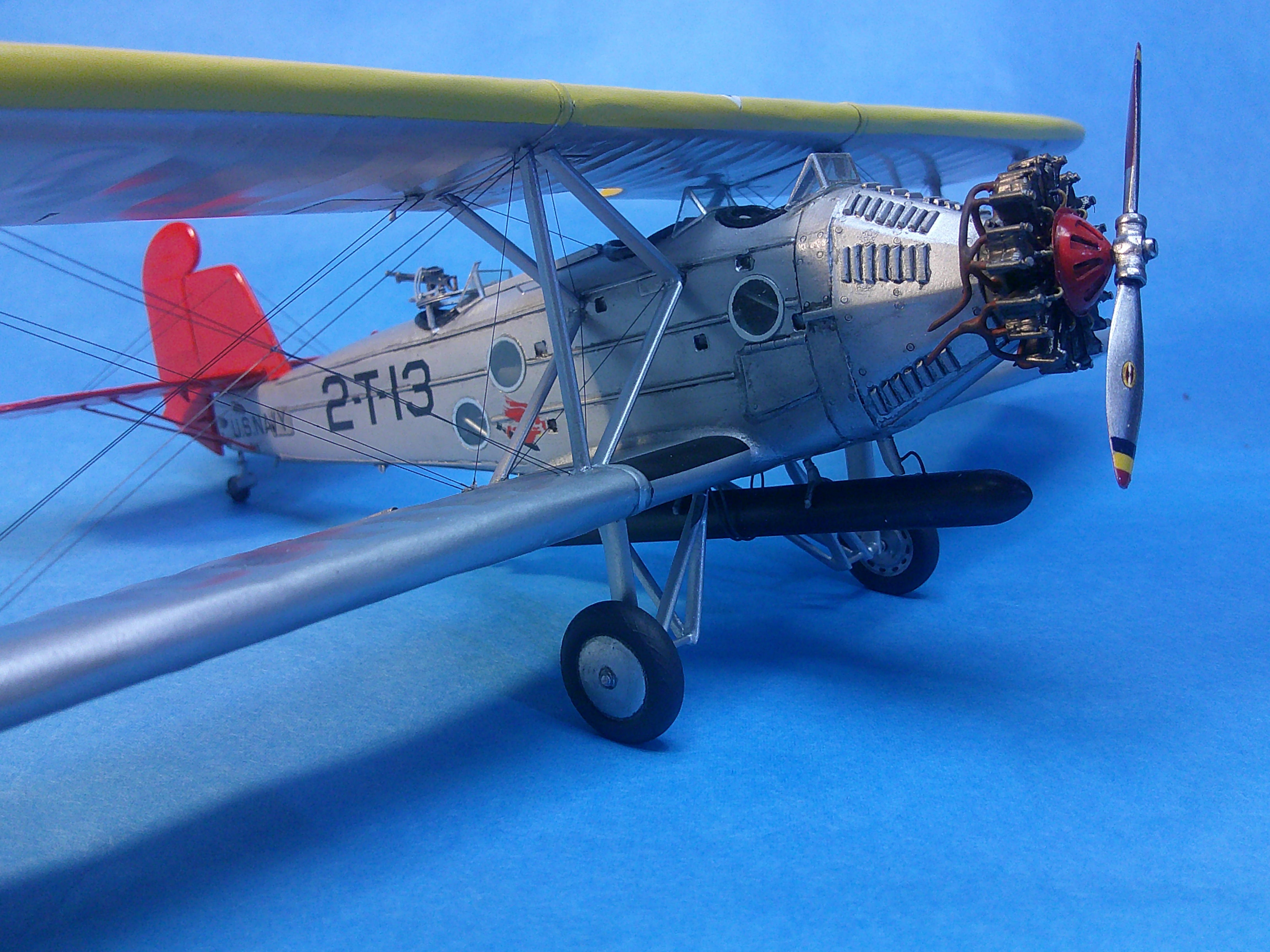
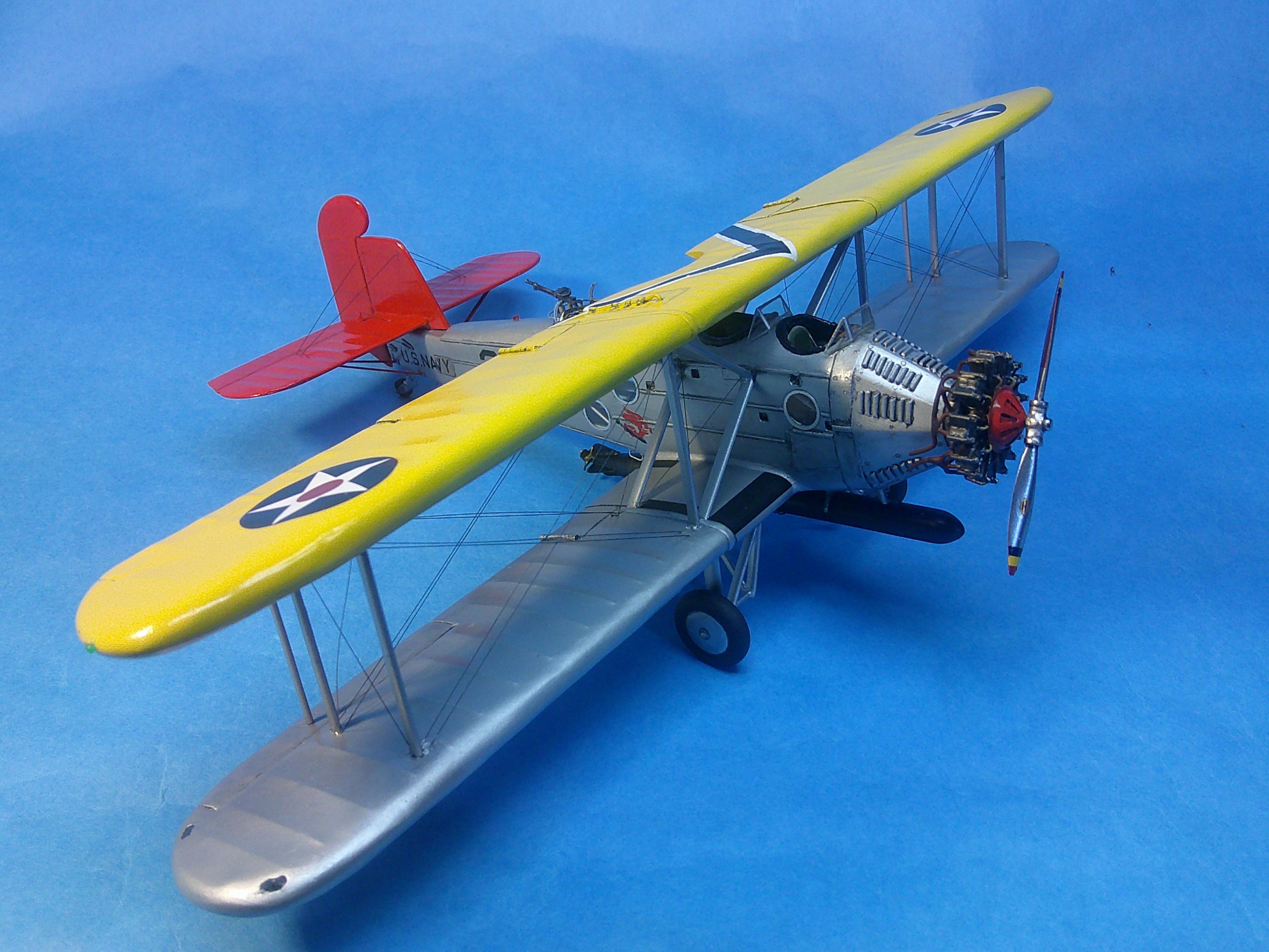
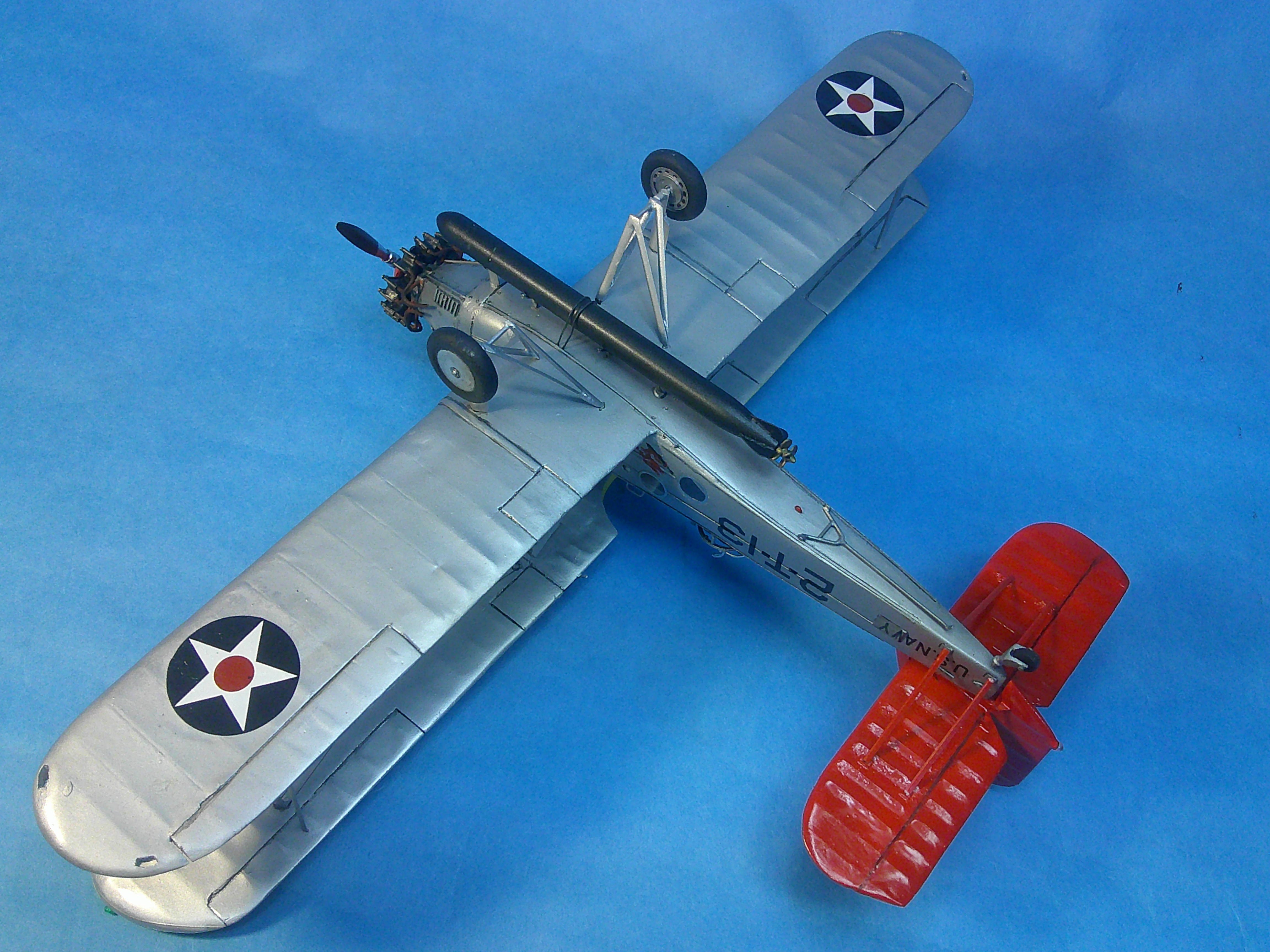
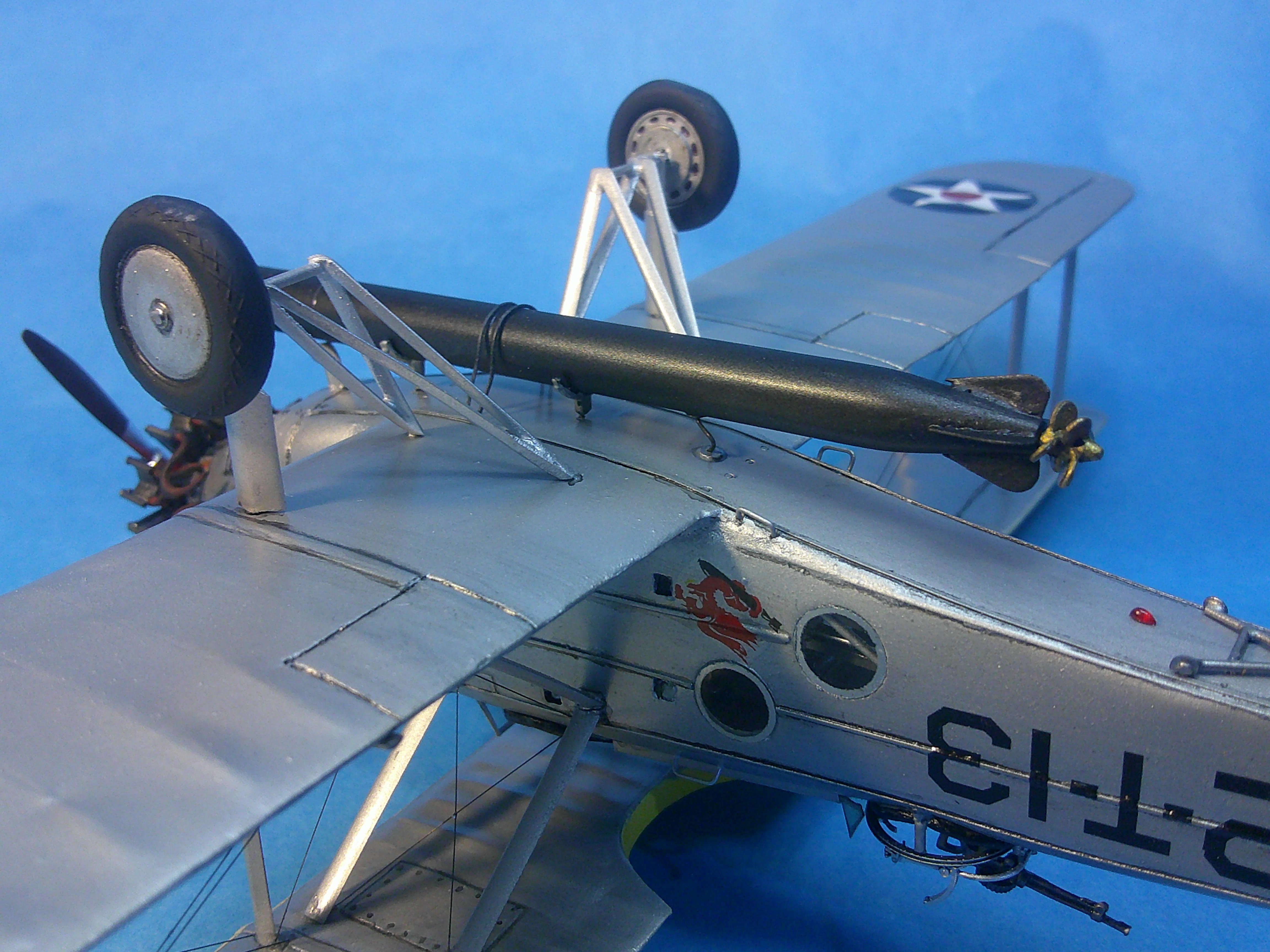
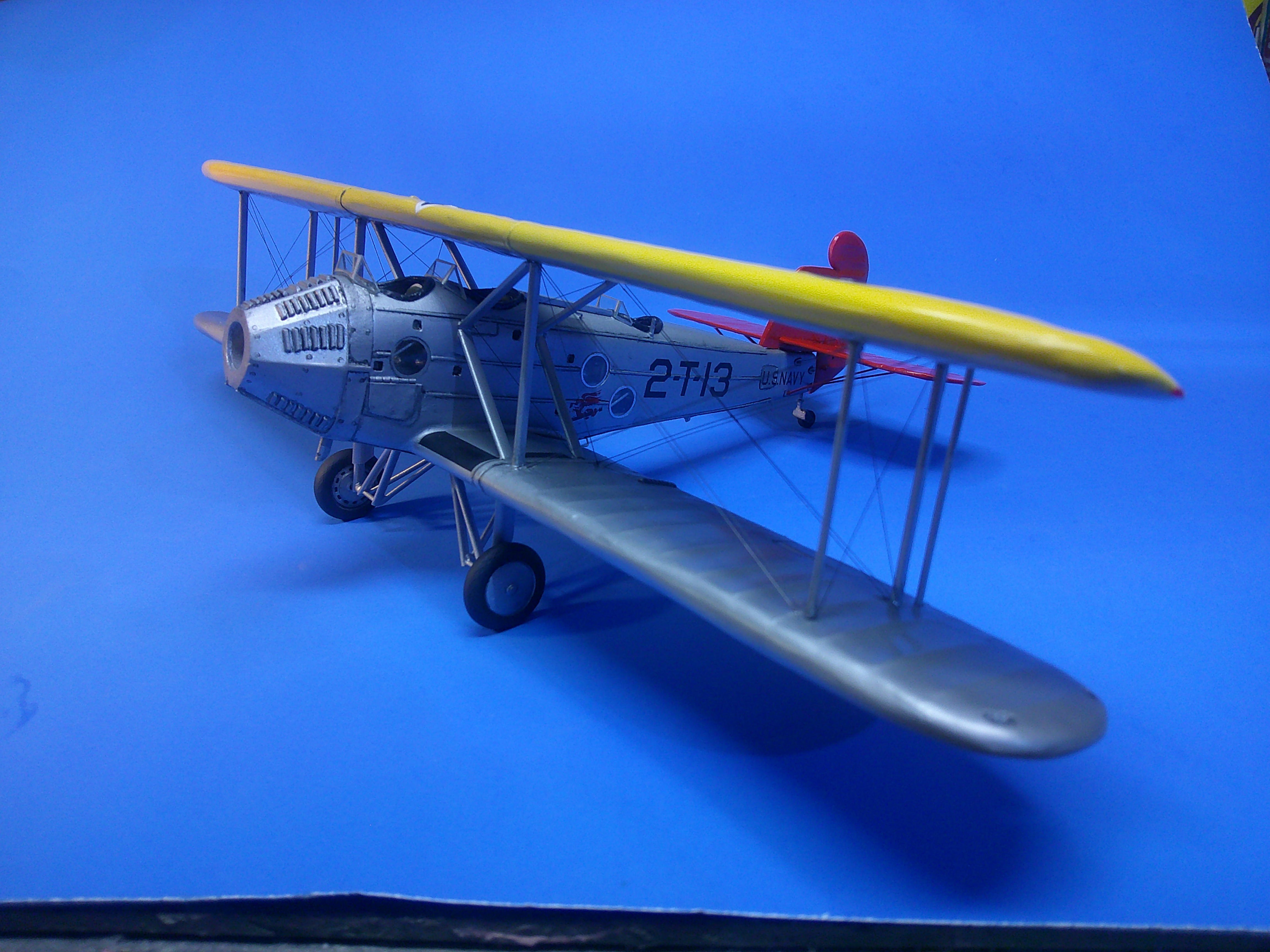
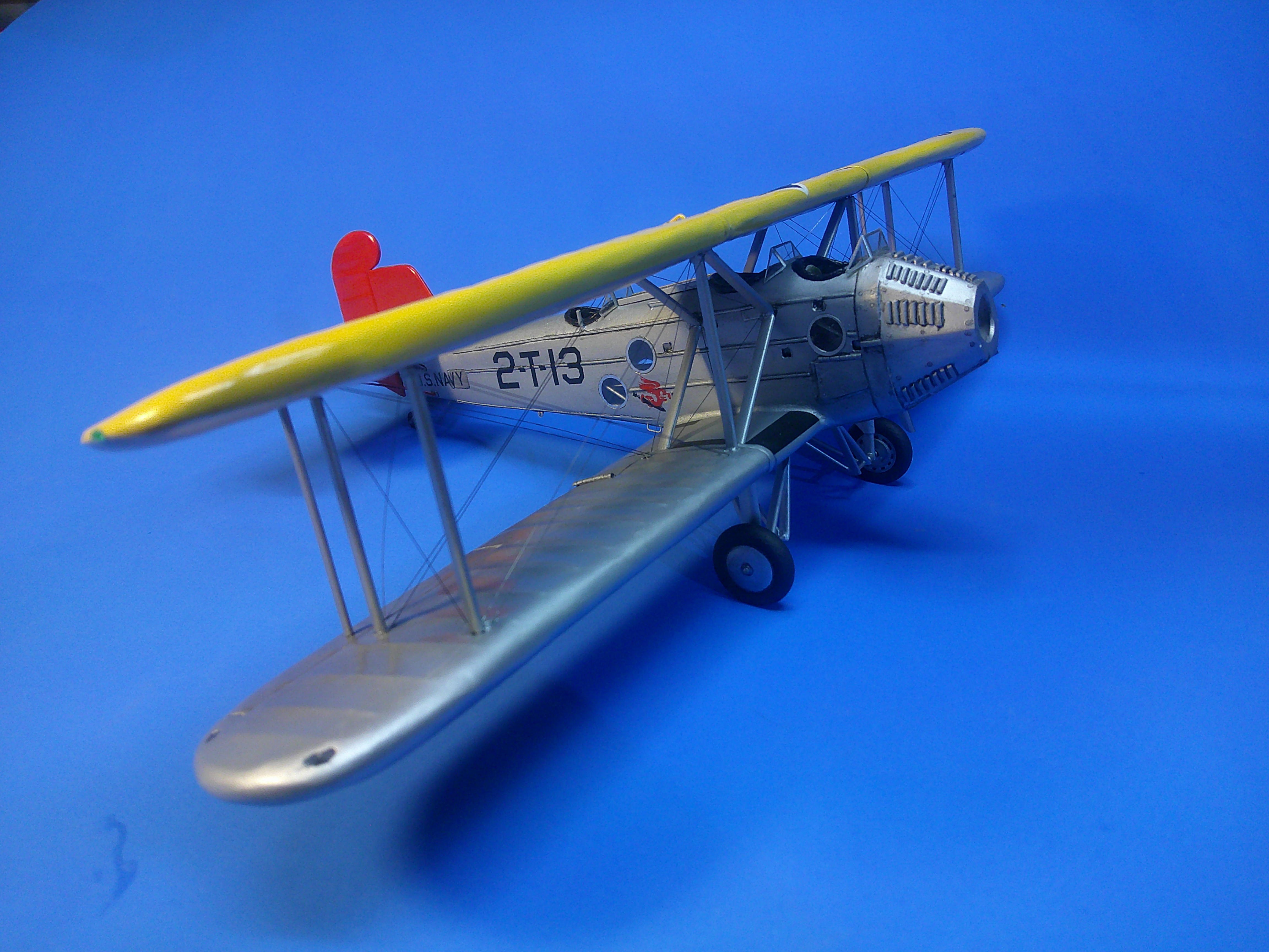
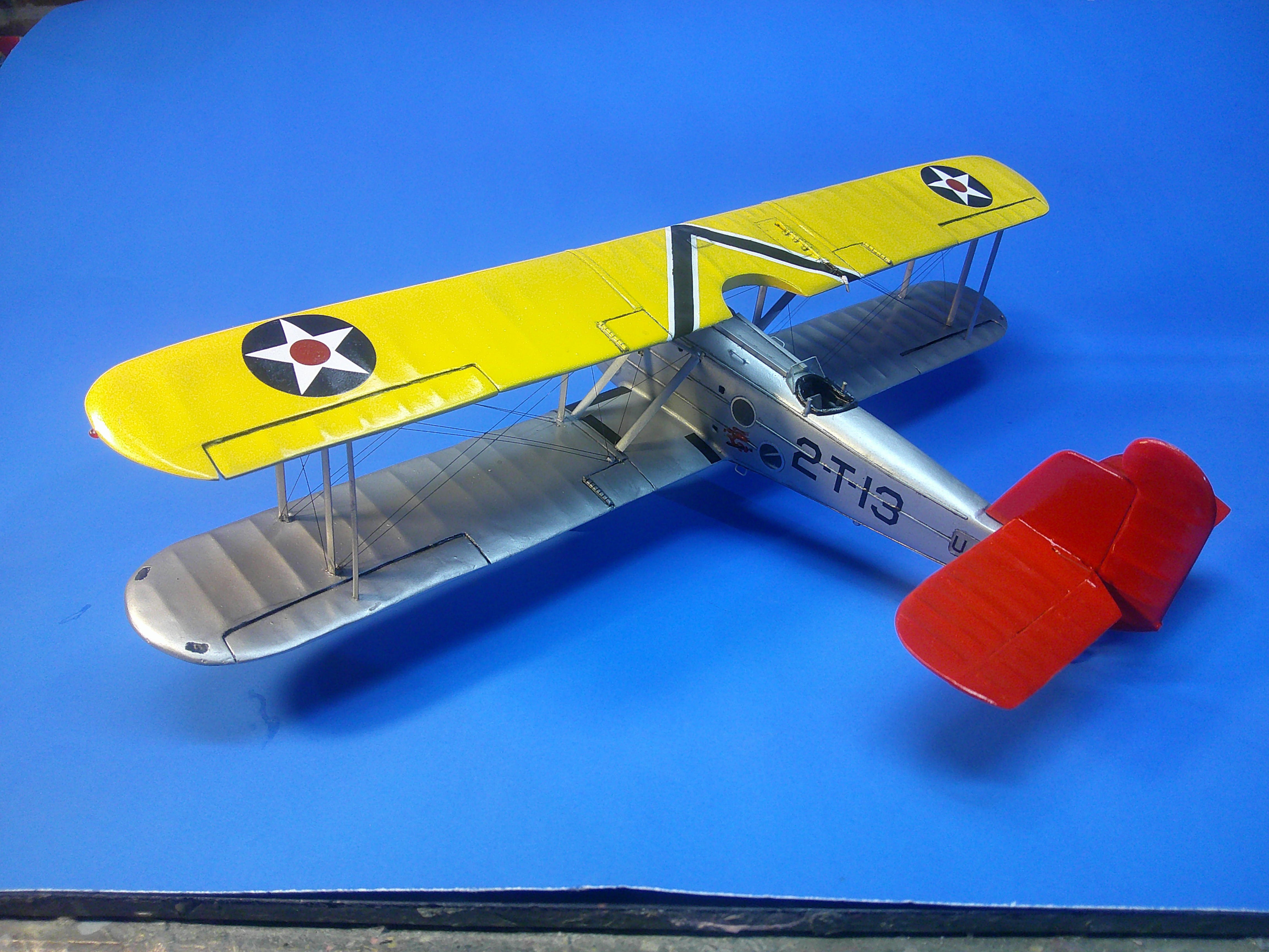
This is my 1/48 scratchbuilt Martin T4M-1 Torpedo bomber. The wings and tail surfaces are plastic wrapped balsa or plastic cores and the fuselage was vacked from a carved balsa form. Even the engine and the prop were rebuilt. The only parts not scratchbuilt were items like the main tires, the torpedo, the Scarf ring, and the Lewis gun. The complete build procedure from day-1 can be found in the "Build" topic area if you wonder what was done or how it was done. It took 3-1/2mos from start to finish. Comments, critiques, and questions are welcome, as always! feels good to have this one done! Gil
-
Calling it done! See more finished pics in the Aircraft topic area! Gil
-
Almost there....... The model is rigged except for 4 wires on the tail, the tail planes are on the model, and so are all of the wheels. The sharp eyed among you will notice there's no "T4M-1" on the vertical tail anymore. That's because the paint CRAZED after I gloss coated it! So.... it had to be stripped, sanded, and repainted and I ain't doing no more decaling! Still some "final" things to be done.... but it should be done in a day or two. More pics when she's finished! Gil