
ghodges
-
Posts
8,164 -
Joined
-
Last visited
-
Days Won
368
Content Type
Profiles
Forums
Events
Everything posted by ghodges
-
Good progress.... bit I do have to ask why you're not filling that gaping hole on the bottom at the same time? Do you plan to do it when you tackle the seam that's immediately behind it instead? In any case your work is a great demonstration of how "old skool" techniques can still be relied on today! Gil
-
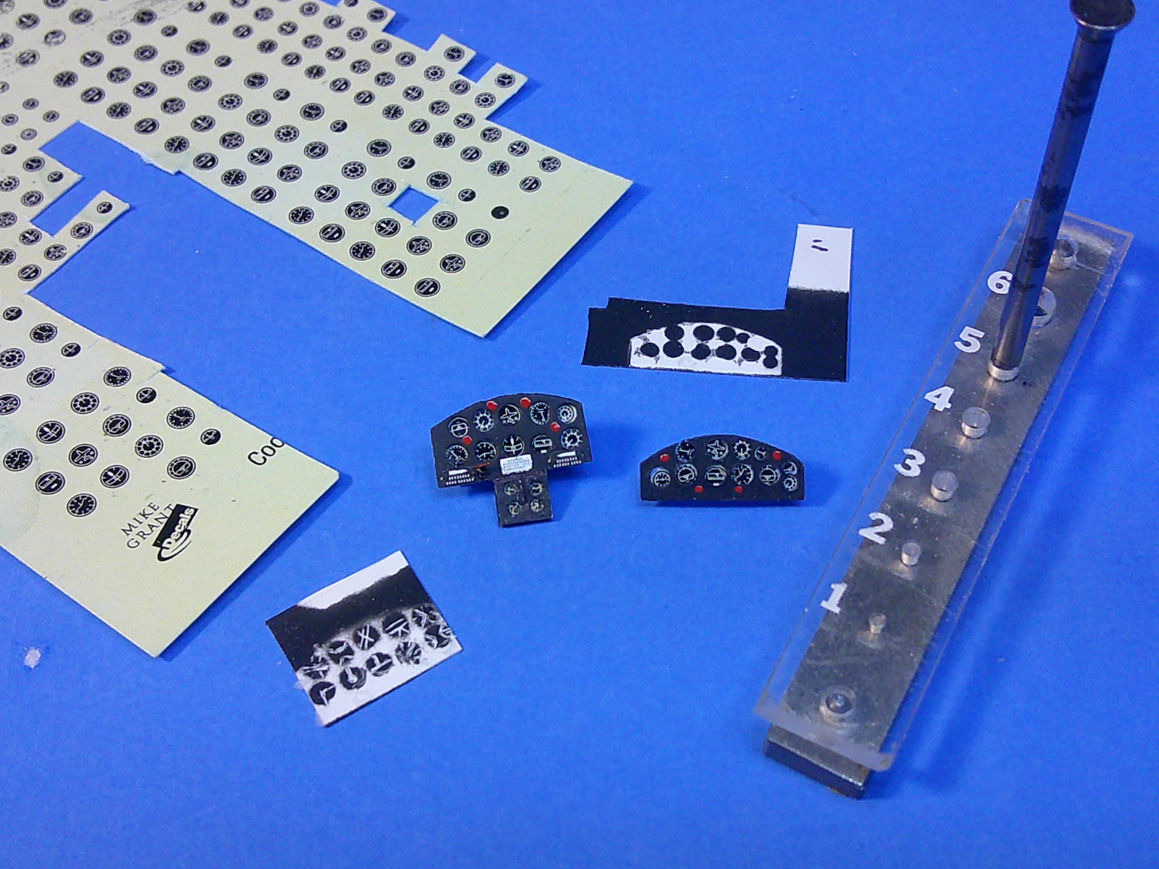
Main IPs are done (or as done as I'm gonna make 'em!).... I started by painting the IPs Tamiya flat black.... I then pried them apart so I could scratch off the markings on each painted black dial..... However! THAT didn't go as well as planned so I switched gears, dug out some Mike Grant instrument decals and punched out each individual instrument and white glued them onto the back of each panel. I then added some spare PE parts and some painted red buttons to finish them up. Interestingly, I believe using the spray can Tamiya flat black may have hindered my initial idea. The scratch-off dial method was originally developed using enamel paint back in the '70s and I think it actually scratches off easier than the Tamiya acrylic/lacquer paint. All I know is I was having more trouble scratching off the paint to make the dials than I have in the past and that's the only difference I could think of. Just file that away for future reference! No pics.... but I also got the interior frame and fuselage interior sides sprayed with their initial coat of metallic aluminum! Perhaps I might have the interior "done" and the fuselage glued together by the end of the week! Gil

-
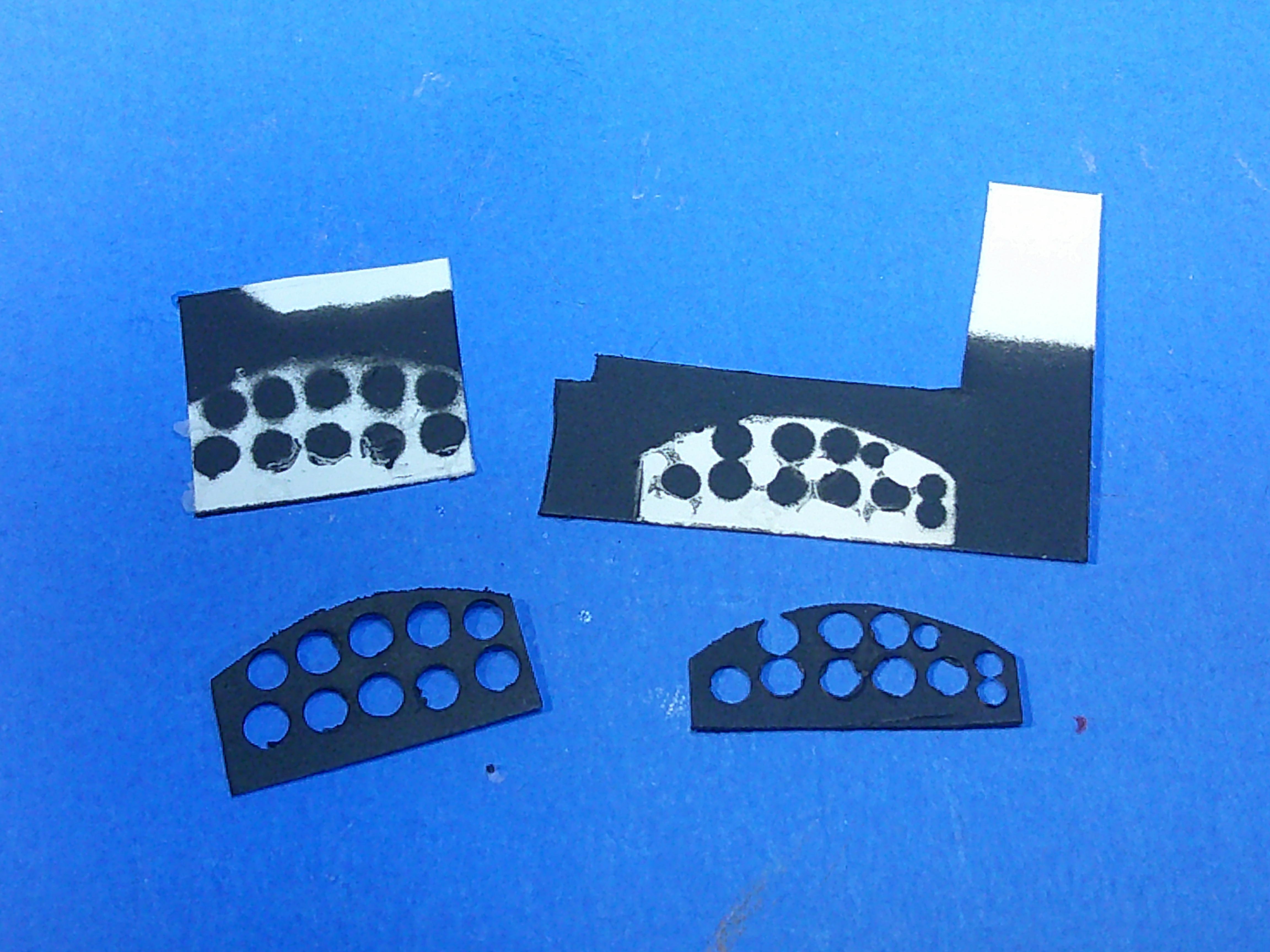
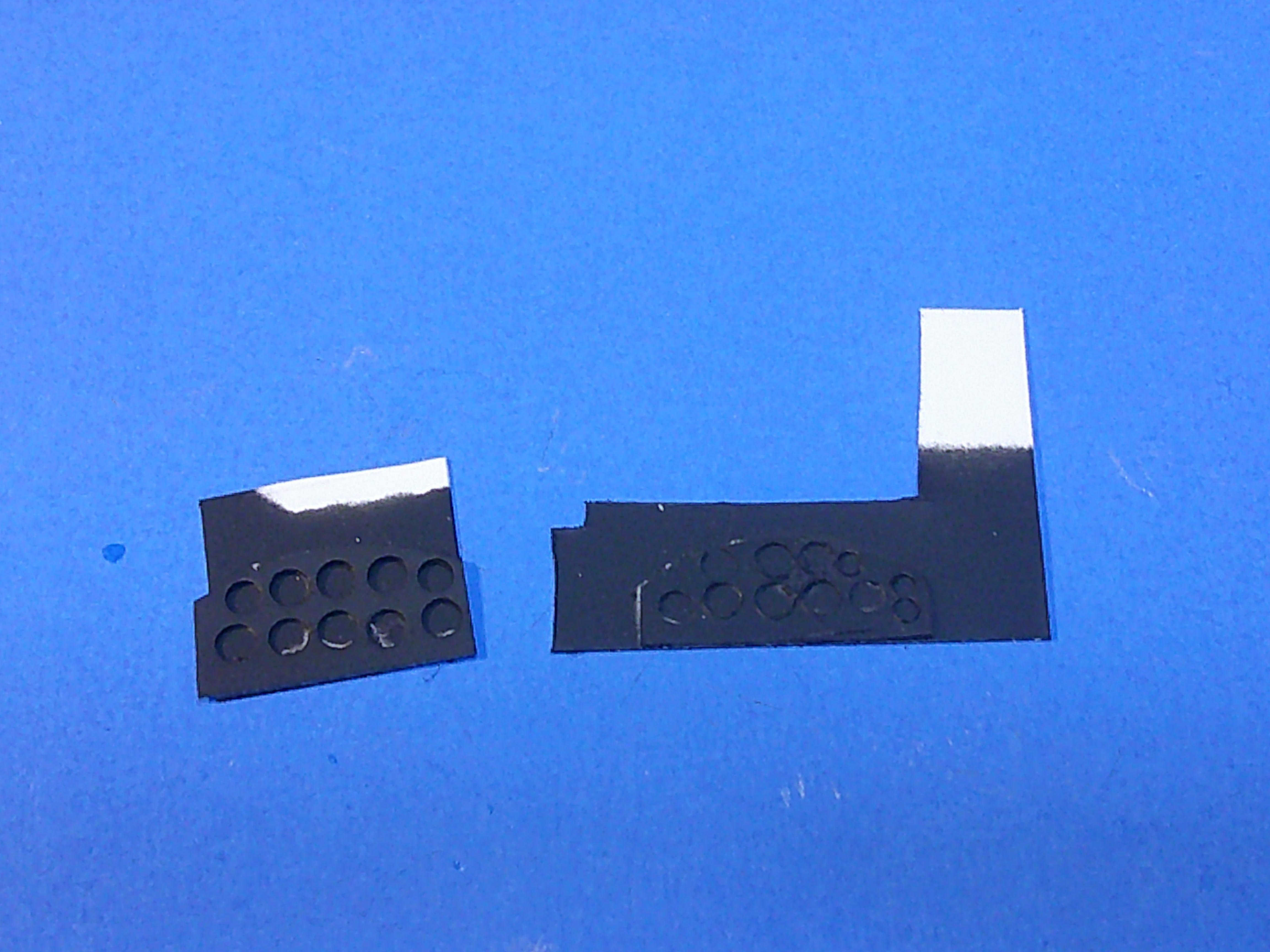
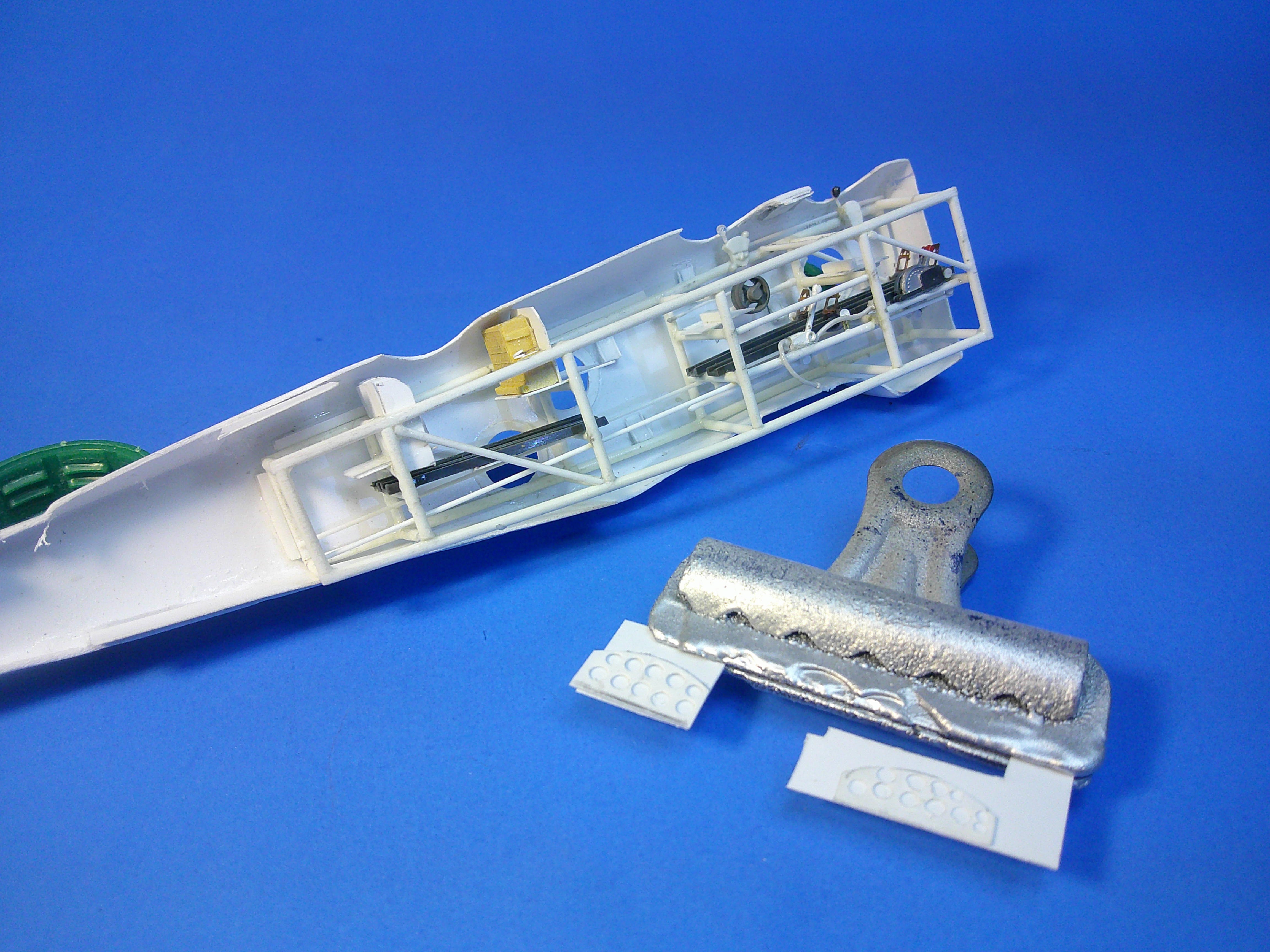
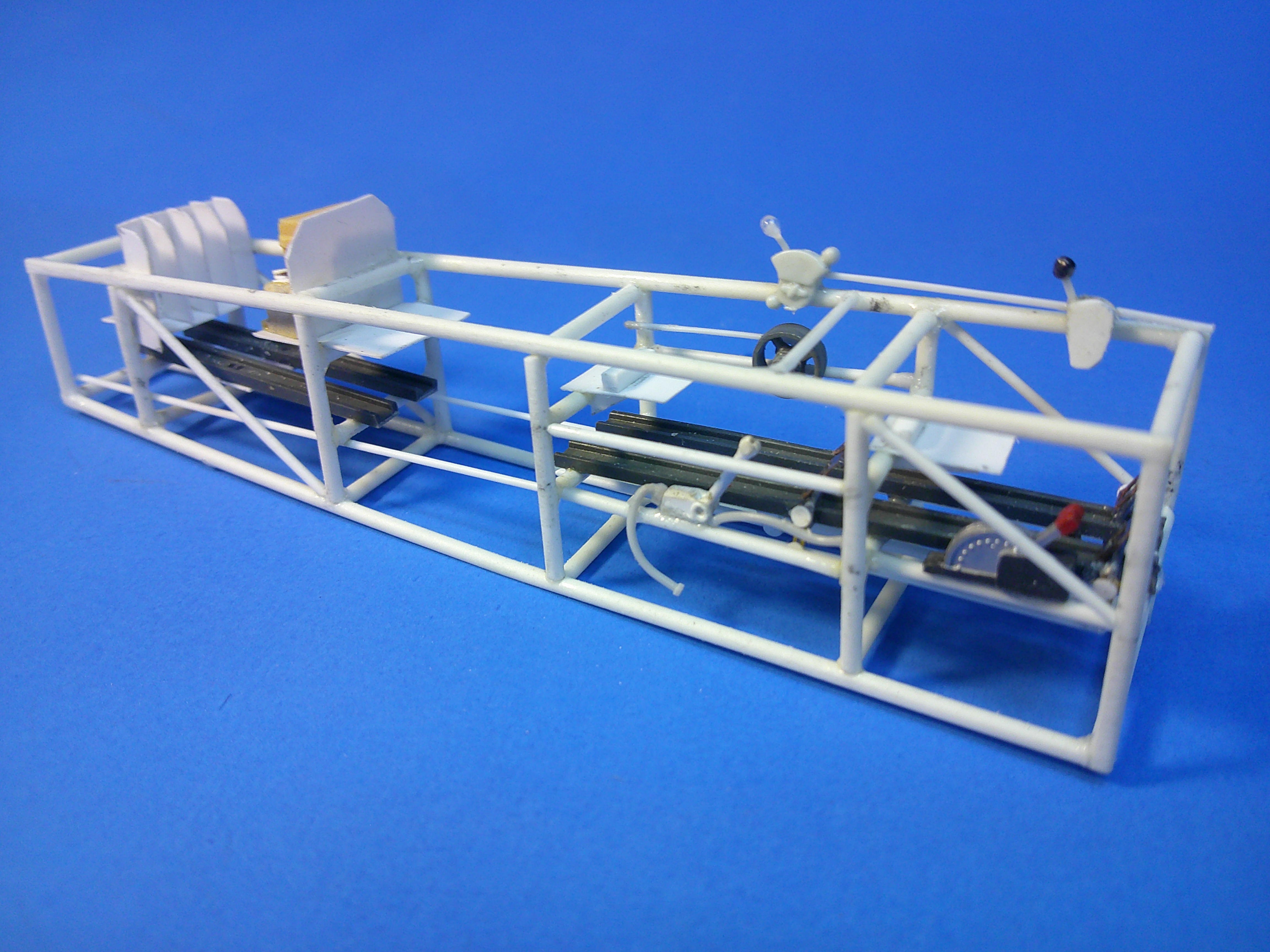
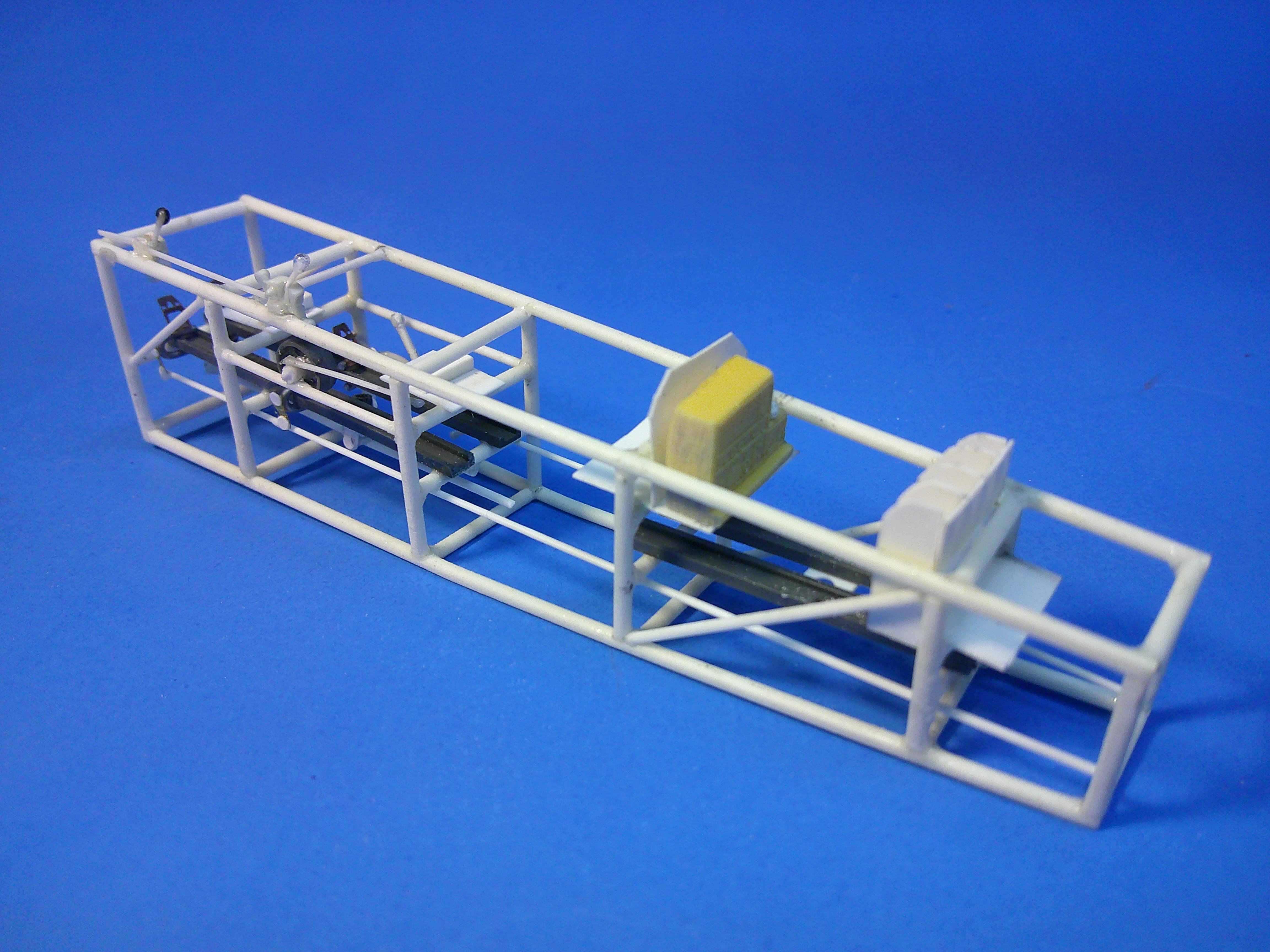
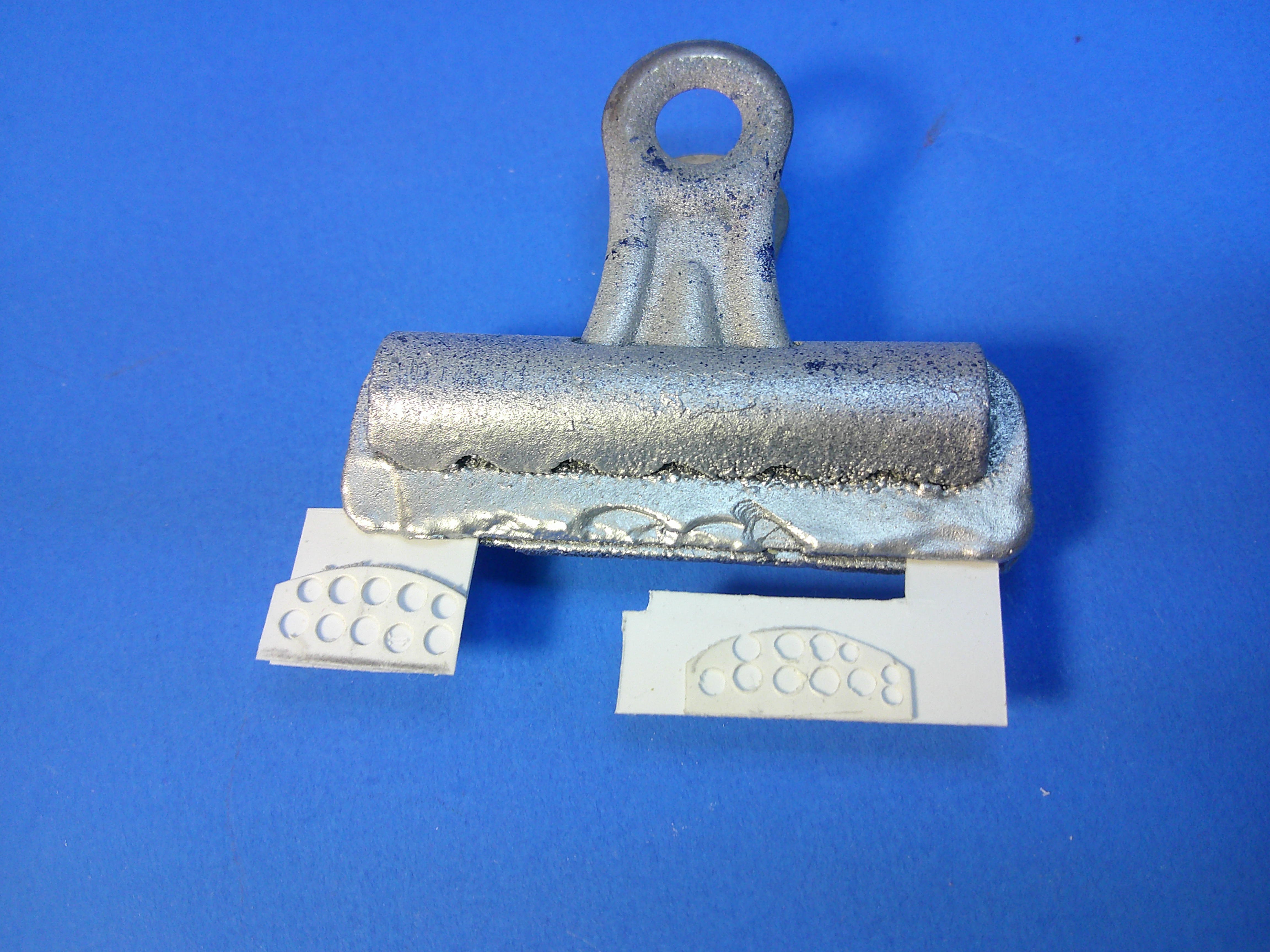
Most all of the interior parts are built now.... Overall view of this week's work.... If you look closely you can see (front to back) the PE rudder pedals and cables, both of the throttle quads and their cable, the torpedo drop control console/handles bottom right front, the trim control wheel on the left center of the middle cockpit along with an emergency hydraulic pump on the right side, and the Lewis gun ammo drum racks in the back of the rear cockpit. This is a view from the other side where you can see the radio (with a sending key out of view) on its rack in the front of the rear cockpit. Not seen is the pivoting seat for the rear cockpit. The main IPs are being built using the traditional sandwich method. The holes for the IPs where made using a Waldron punch and die set. These assemblies will be sprayed black and then the fronts pried from the backing sheet so the black instruments can then have their individual markings scribed in place. More pics of that when they're done. Gil
-
Impressive camo job! Was it all free-handed or did you do some sort of masking? Very sharp work in either case! Gil
-
Nice attention to the details! God bless your move! Hope it goes smooth and I look forward to when you've got your shop set up again and can post things. Gil
-
Started making cockpit parts today for the scratchbuilt 1/48 T4M-1; working on getting the resin seats installed at the right heights, installing foot channels evenly at their correct heights, and making up the control wheels with their actuator/torque tubing. All of this was done pretty much by repeated trial and error test fitting. There's still a lot of other details to be added to the interior yet including the entire rear cockpit. The seats and sticks are designed to be able to be added late in the build. Test fitting the assembly to the fuselage for the seat heights and positions compared to the cockpit openings. More pics when the interior is more or less complete! Gil
-
Superb Skyray! Your got even more out of what's a nice kit to start! Thanks for sharing! Gil
-
Got a couple of major jobs done today.... I got the fuselage windows made. I started by making "rings" to fit on the inside of each window JUST slightly smaller than the opening. This made "seats" that each clear window can later be slid onto which will allow me to add the windows very late in the build. The bottom fuselage has 3 windows sitting in place, and you can see the other 3 windows at the bottom of the pics. They were made with a punch of the appropriate size. I also got the interior tubular frame built. The frame was made using plastic rod and built by fitting parts inside the fuselage and also matching to the plans on hand. It was done partly with measurements and partly by "mark-1 eyeball". There's still more supports to be added for detailing, but this makes up the basic frame. These 2 pics show the test fitting of the tubular frame into the fuselage to be sure it fits ok. There's still a l-o-n-g way to go to build up all of the interior details, but at least I now have a frame to hang everything on and within! Gil
-
I've started adding details to the fuselage exterior using strip stock for ribbing, half round rod for hinges, and plastic tape (blue) and sheet plastic for access panels. Hand holds/steps have also been opened up and then boxed in. I may throw a coat of primer on it all just to get a sense of how it'll look under paint. Gil
-
Academy 1:72 PV-1 Ventura - "Eyes of the Empire Express"
ghodges replied to Chris Bucholtz's topic in Aircraft
Great looking legacy build Chris! Is that a squadron marking or personal artwork on the fuselage behind the star? Gil -
Started working on the fuselage halves... Sanded these out and then added the alternating plastic strips needed inside the seams to keep the thin edges of the plastic from folding over each other when test fitting the halves together. The plans you see were used to mark and then guide cutting out the 3 windows in each side. Here's the fuselage taped together for a test fitting with the nose in place. All of the window and cockpit holes were first opened with a drill bit. Next, I used a router bit in a motor tool to grind out most of the opening, followed with another conical sanding bit to finish out each opening. I used the lower speed on my 2-speed battery powered tool so to avoid melting the plastic while grinding it away. Gil
-
Nice start! Man... what a difference between those seats in both size and detail! Gil
-
A significant step forward! I have vacuform parts! Well.... I pulled about 6-7 shots (more than seen here) on my machine with spurious results..... but I'll reserve final judgement until they're all cut out and I've tried fitting them together. I only need 2 halves to work! The nose was very problematic with the draped edges as seen. Luckily I do NOT need a vac (hollow) nose and can use the master on the model if needed! It's good to know that my vac box, metal frame and clamp system "works" even if the parts look VERY amateurish compared to what you get from commercial vac kit makers! More pics after I get some parts fitted together. Gil
-
Maddog Manufacturing Opening for 2026
ghodges replied to Mark Deliduka's topic in Photos: On the Bench
Excellent progress Duke! I'm guessing both of the LST's are "modern" ones as they seem to be the same type so that the Japanese one will merely be a difference in numbers and name? Also, why does the WC truck have a Brit roundel on the hood but says "American Field Service" on the door? As usual I'm stunned by the amount and variety of subjects you're able to keep track of and work on! Gil -
Still inching along on the torpedo bomber..... Got the nose cut off of the fuselage and glued sheet plastic to it to add the flat panels around it. I felt this would be easier than trying to sand each area of the nose AND keep the panels symmetrical. These 2 pics show the fuselage halves after having been split back apart along the original glued paper divider and also the angles of the nose panels on its sides, top, and bottom. Sometime scratchbuilding a model requires more than just building the model.... in this case I needed to make adjustments to more efficiently use my vac table..... I have a BIG table, measuring 22' wide x 28" long! This will come in very handy for one future project I have in mind, but it's MUCH bigger than needed for this torpedo bomber and would waste a lot of sheet plastic. Note the marked off rectangle in the center..... this is where a smaller raised platen will go to vac my parts. All of the holes outside of that area will have to be sealed with tape. The answer is to vacuform smaller sheets of plastic.... big enough for the parts, but not as big as the table. I found a metal document frame at Walmart that's 11"x14" and took all of the glass, matting, and other stuff out of it to leave the bare frame. The sheet plastic is simply clamped to the frame. This will be popped into the oven to heat the plastic until it sags so I can then throw it on the table and vac my parts (hopefully!). I made a smaller raised "platen" out of peg board to set onto the center of the vac table with holes that match the vac table. I've placed the parts here to give an idea of how they'll look when ready to vac over EXCEPT that they'll each have some material added on their undersides to slightly raise them from the platen so the vacuum can (again, hopefully) circulate a bit under the parts as well as around them. Ain't "do it yourself" fun? Lastly.... you might be wondering where do you get the sheet plastic? You order it from a plastic supply house! This is 5 sheets of styrene (3 of .02 and 2 of .03) rolled up in there, each one 40"x70". Hopefully that'll be enough for anything and everything I might do for years to come! More pics after (AND IF!) I can get this all to work! Gil
-
Lovely build and hat's a beauty of a scheme on that biplane Ron! Although I understand it to a degree, I think many "modern day" builders are missing out on one aspect of modeling when they ignore older kits like that while waiting on a "new tool" version. Oddly enough, the same compliment can be said about the Aurora 1/48 biplane designers when compared to their 1/48 WWII fighter models; the biplanes where MUCH better engineered and more accurate! Good to see you've lost none of your sprue stretching skills! Gil
-
Unique indeed! Thanks for letting us tag along the build! Gil
-
Excellent looking finish! It's sort of an odd scheme that doesn't seem to fit any sort of attempt at true camo. Since the colors seem to all run vertically do you know if (perhaps) it denotes different types/thicknesses of skinning used on various areas for more strength in those places, or just maybe different manufacturers of the same skinning using different dyes which they then cobbled together? Gil
-
Ooo! Looks like a real snap-shot taken through the door! Nice! Gil
-
Found a boo-boo in my build.... I JUST found a small anomaly in my T4M-1 build.... evidently there should be NO REAR inner vertical wing struts, as seen in the pic above! The lack of a vertical strut at the rear of the wing fold break is something I should have noticed earlier. The plans I have do not have a "rear" view and the rest of the plans imply that the struts would be there like most other biplanes of that time. But after studying pics of the real thing, they're just not there! Luckily it's an easy fix at this point! Just leave them off! It always pays to quadruple check your references! Gil
-
I'm pronouncing "phase 1" of my scratchbuilt 1/48 Martin T4M-1 torpedo bomber as done! These pics show the wings, empennage, and landing gear mocked up with the balsa fuselage. I went this route reasoning "why bother vacking a fuselage if I couldn't build the rest"? Now I believe it's time for phase 2 and to turn my attention to the fuselage to determine what details need to be added before splitting it apart to be vacked. More pics after THAT's been done! Gil
-
What method are you using to induce the curvature of the strip plastic around those edges? Are you heating it first, or just bending it with your fingers and gluing it as you go? Gil
-
Got the main landing gear built for the T4M-1 torpedo bomber. Each one consists of 11 pieces of airfoil strut, wire, and a small bit of tubing. More pics after I get the tail wheel built! Gil
-
Maddog Manufacturing Opening for 2026
ghodges replied to Mark Deliduka's topic in Photos: On the Bench
Good looking progress as it seems Duke Inc. is doing it's part in the "re-industrialization" of American modeling! 😁 Gil -
I have a most of a bag of what I believe was made by Contrail back in the day, with a variety of widths and all about a foot long. I also have a drawer with left over strut stock (including some sturdier types) but they're all 3"-6" long; which may do for trying to make the landing gear legs. I don't know of anyone who makes and sells extruded airfoil strut stock these days. It sounds like JUST the thing an enterprising 3D printer could make and sell though! The market for it is much smaller these days than 20-40yrs ago, but it is still out there. Gil