
ghodges
-
Posts
8,164 -
Joined
-
Last visited
-
Days Won
368
Content Type
Profiles
Forums
Events
Everything posted by ghodges
-
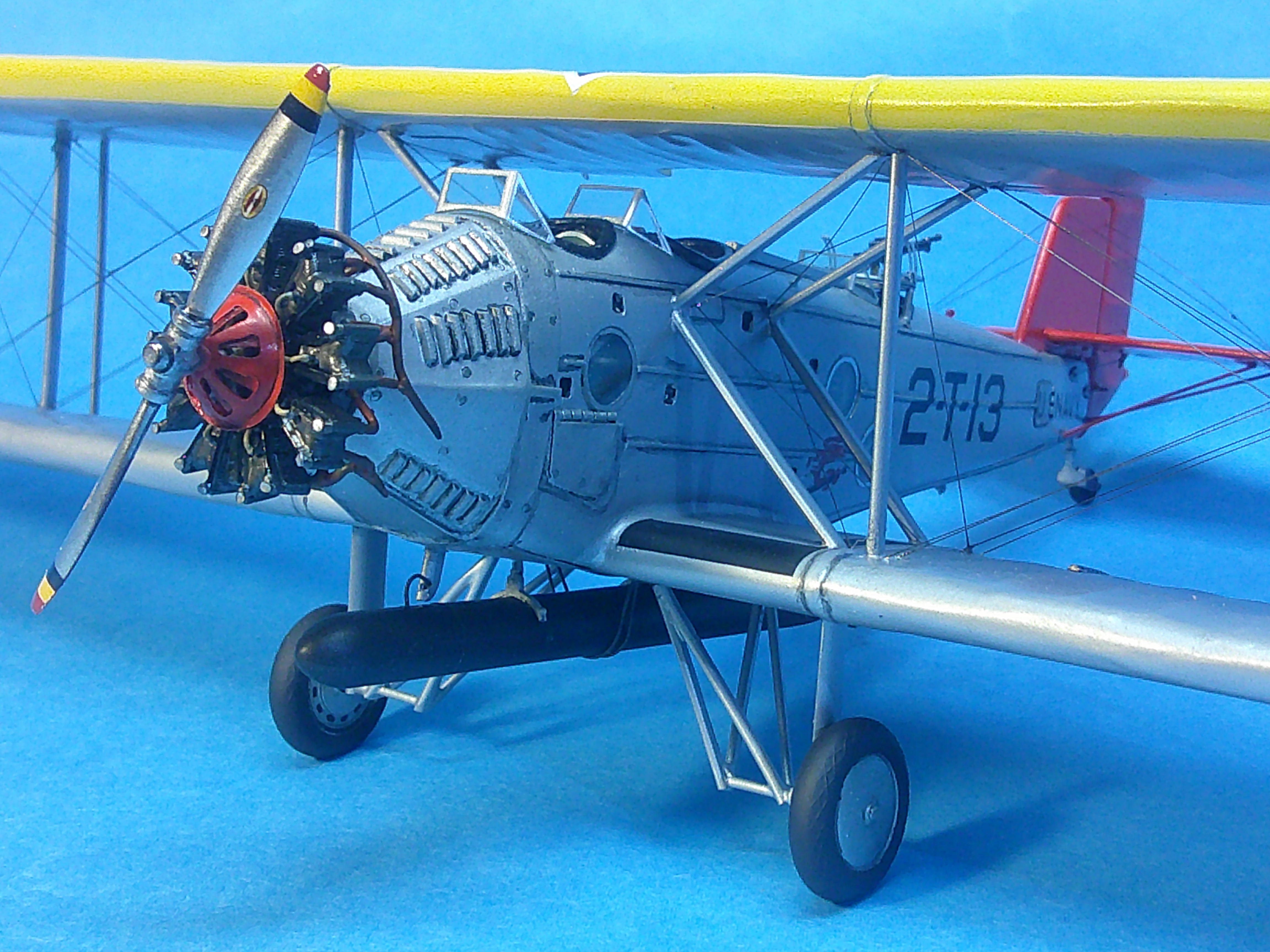
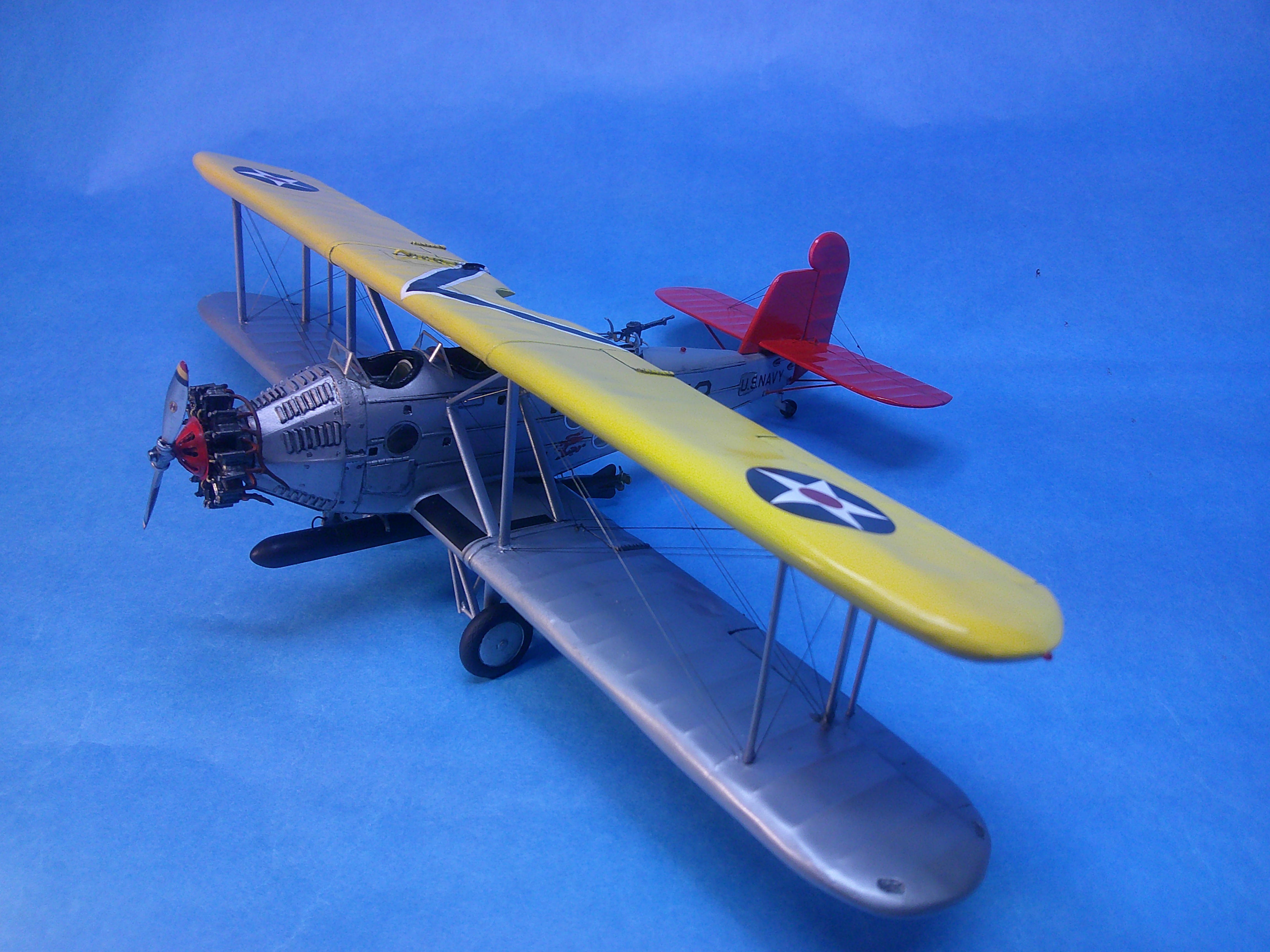
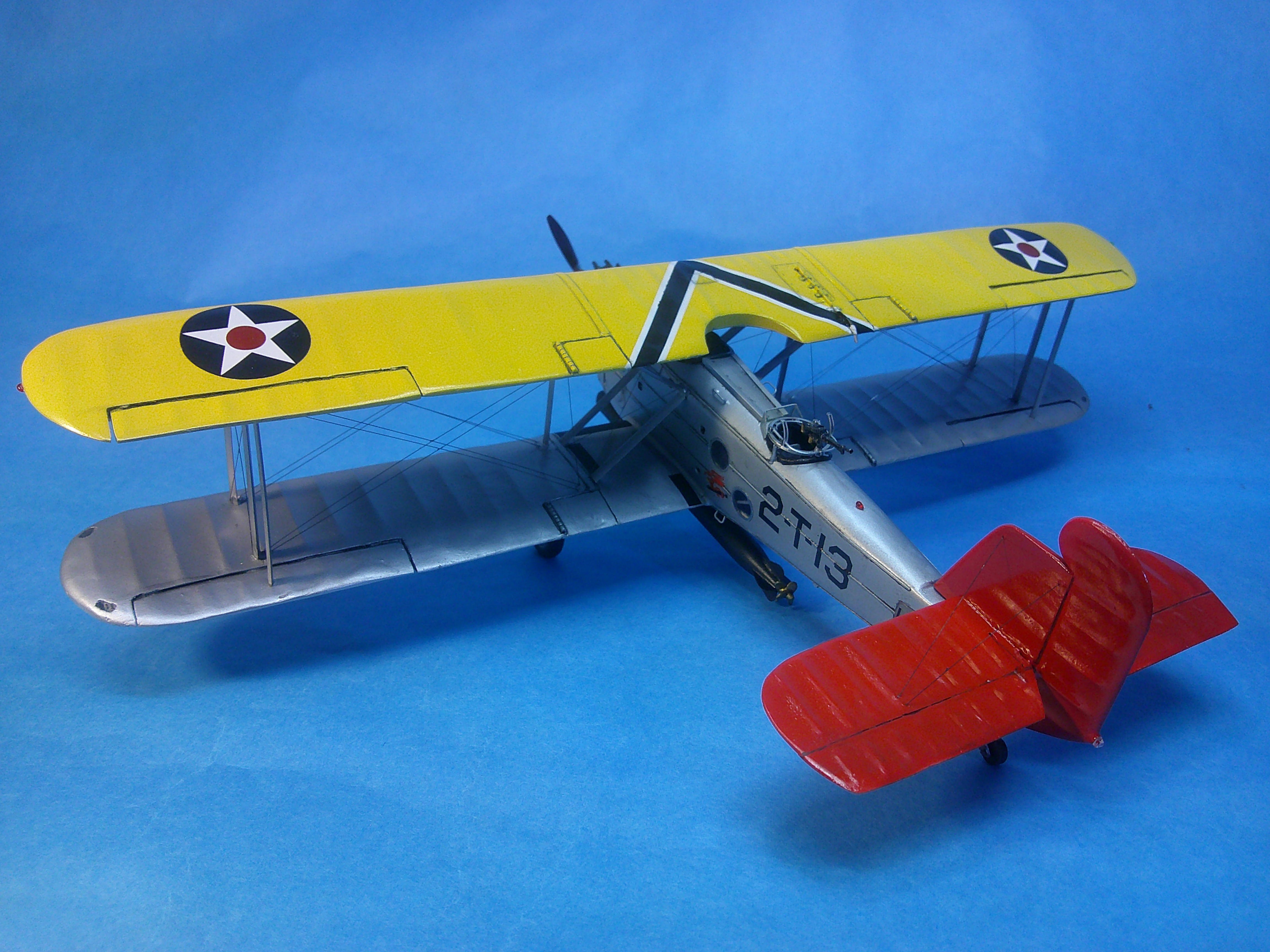
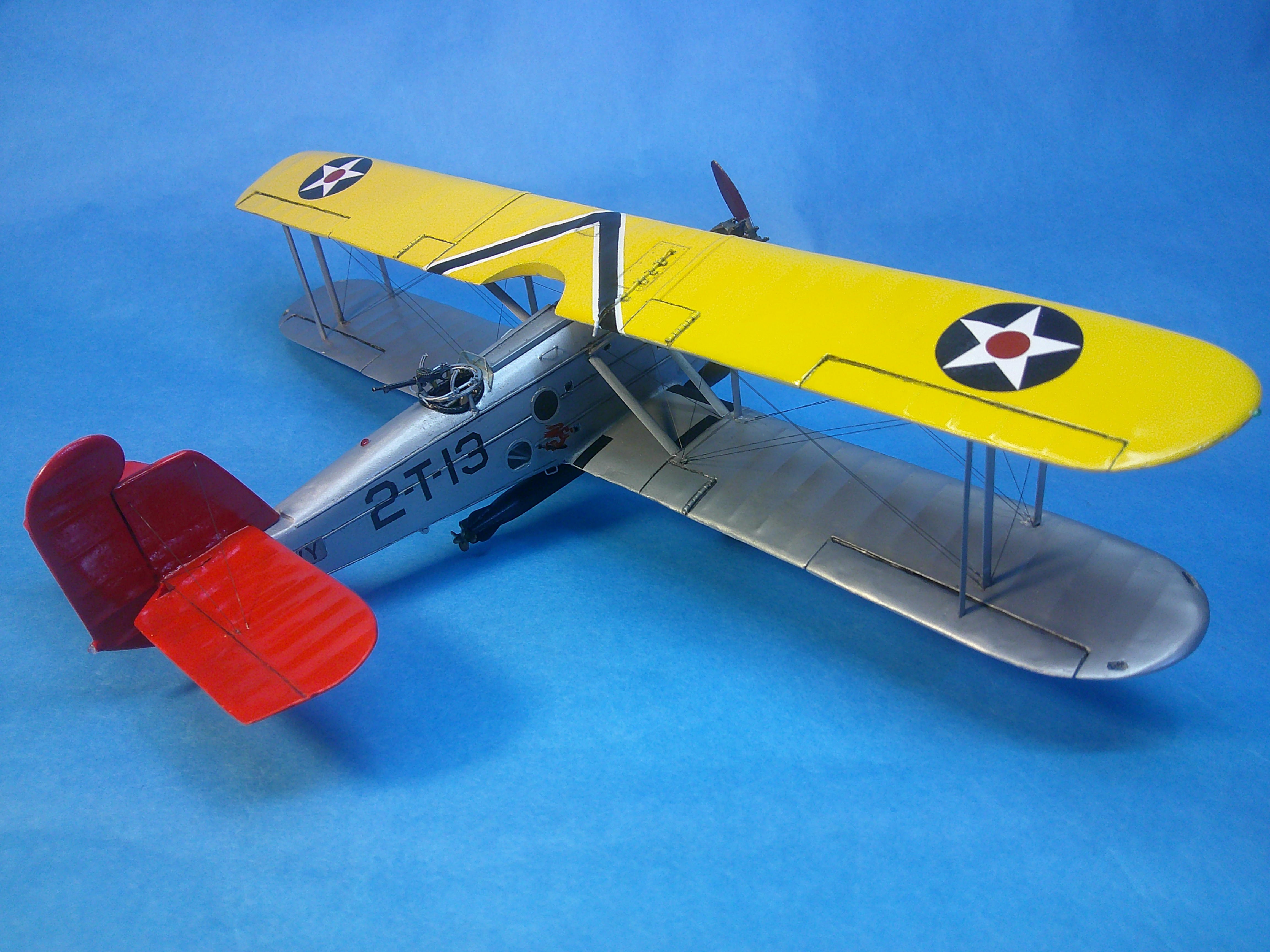
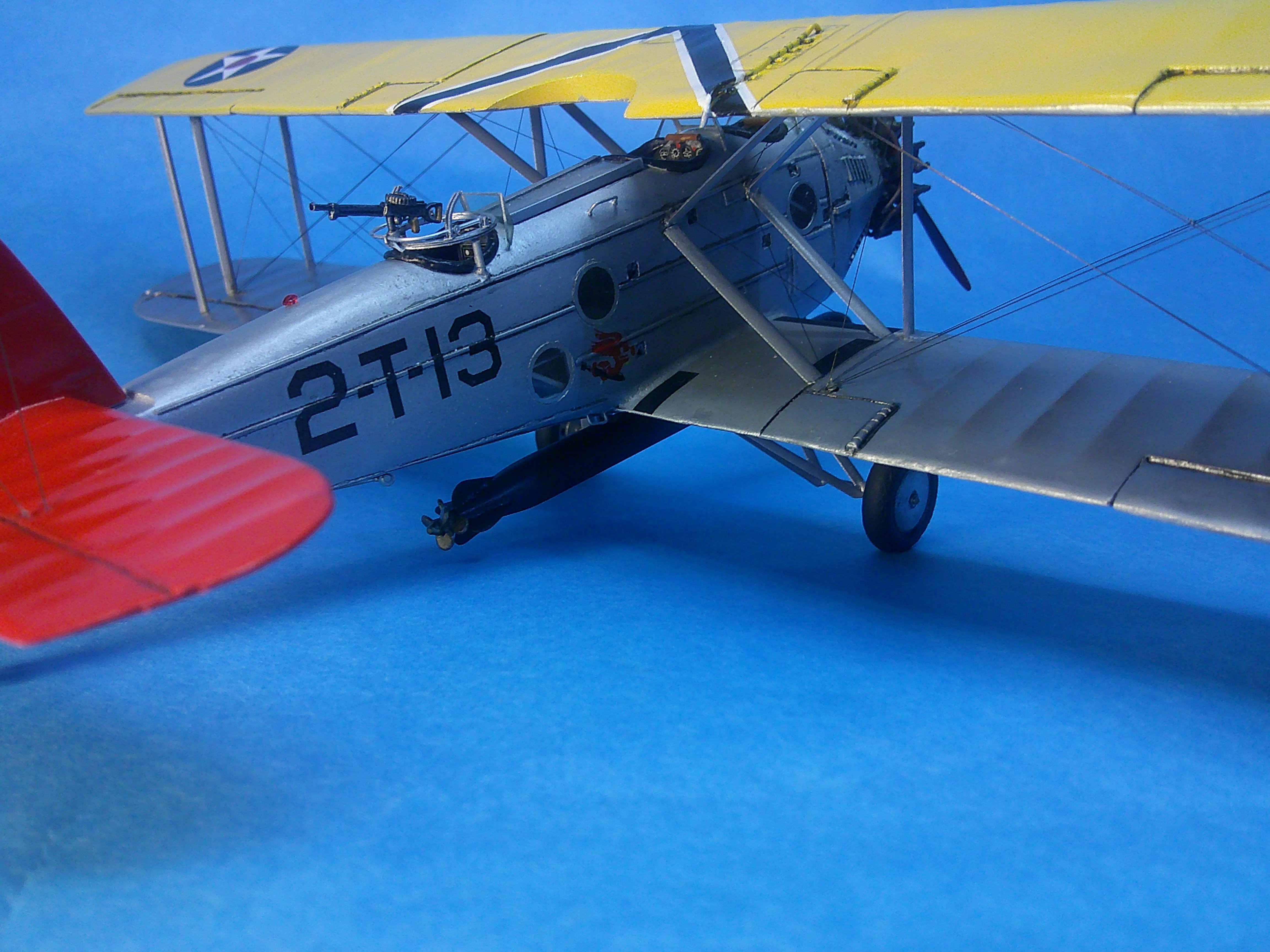
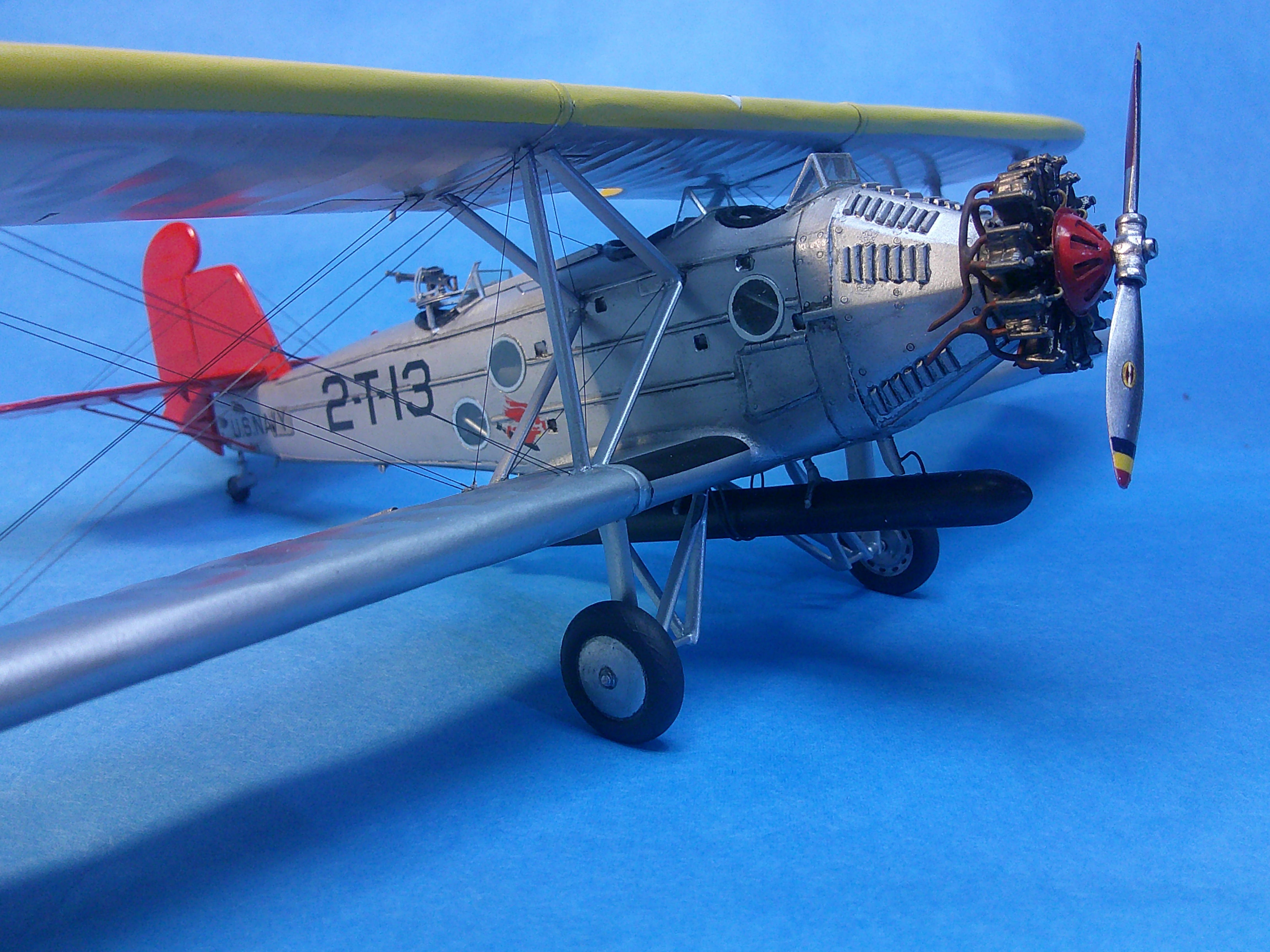
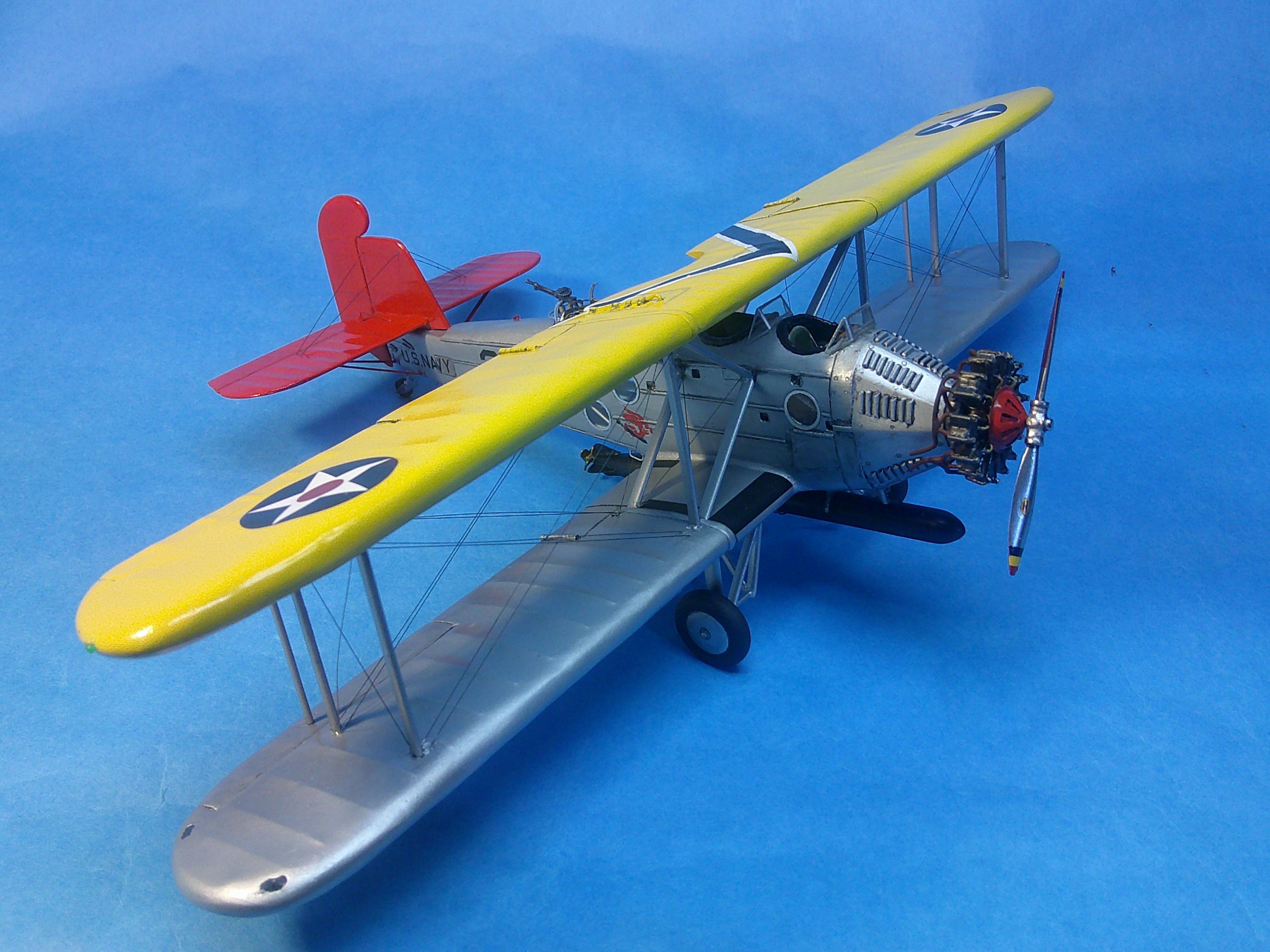
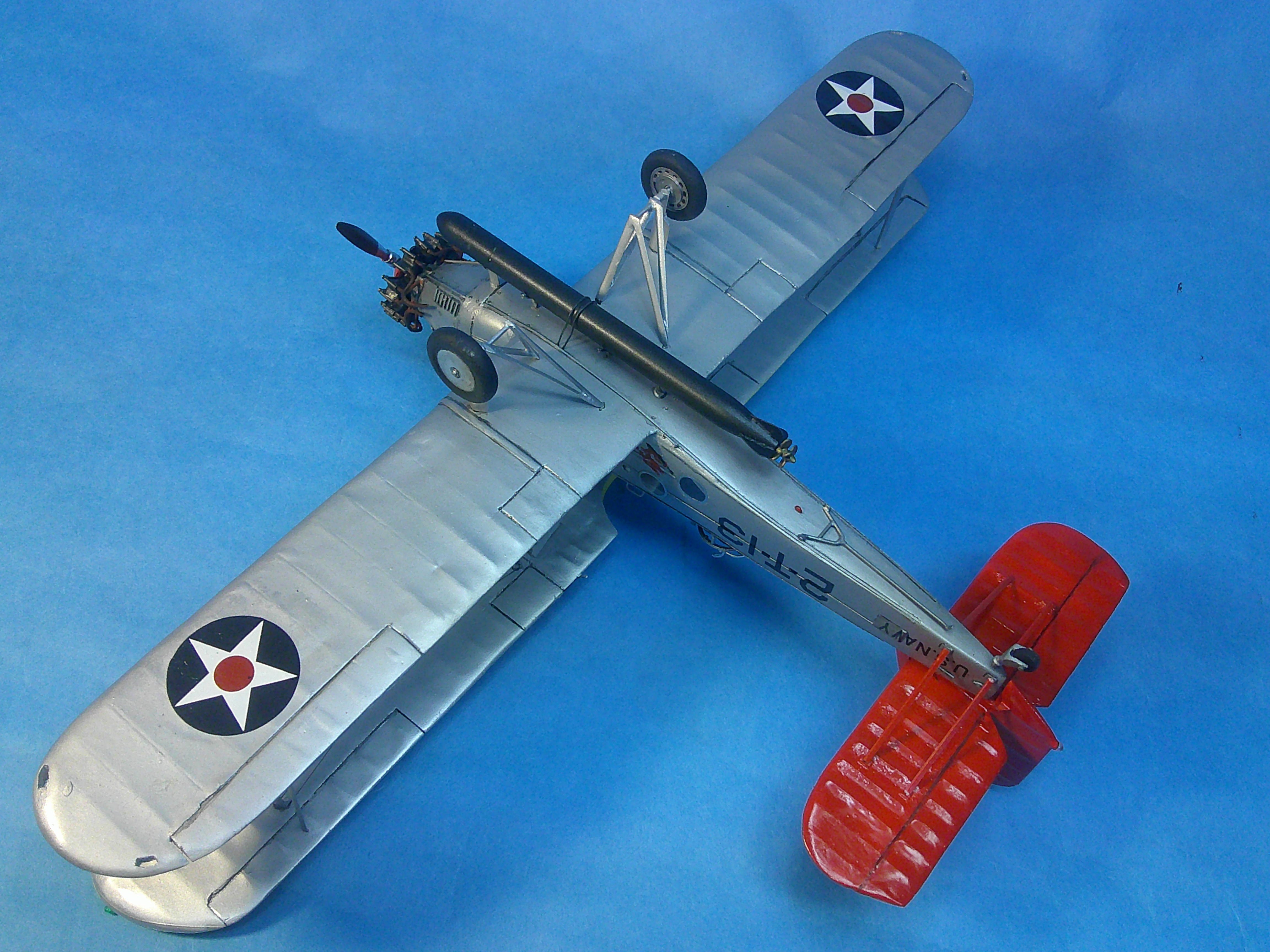
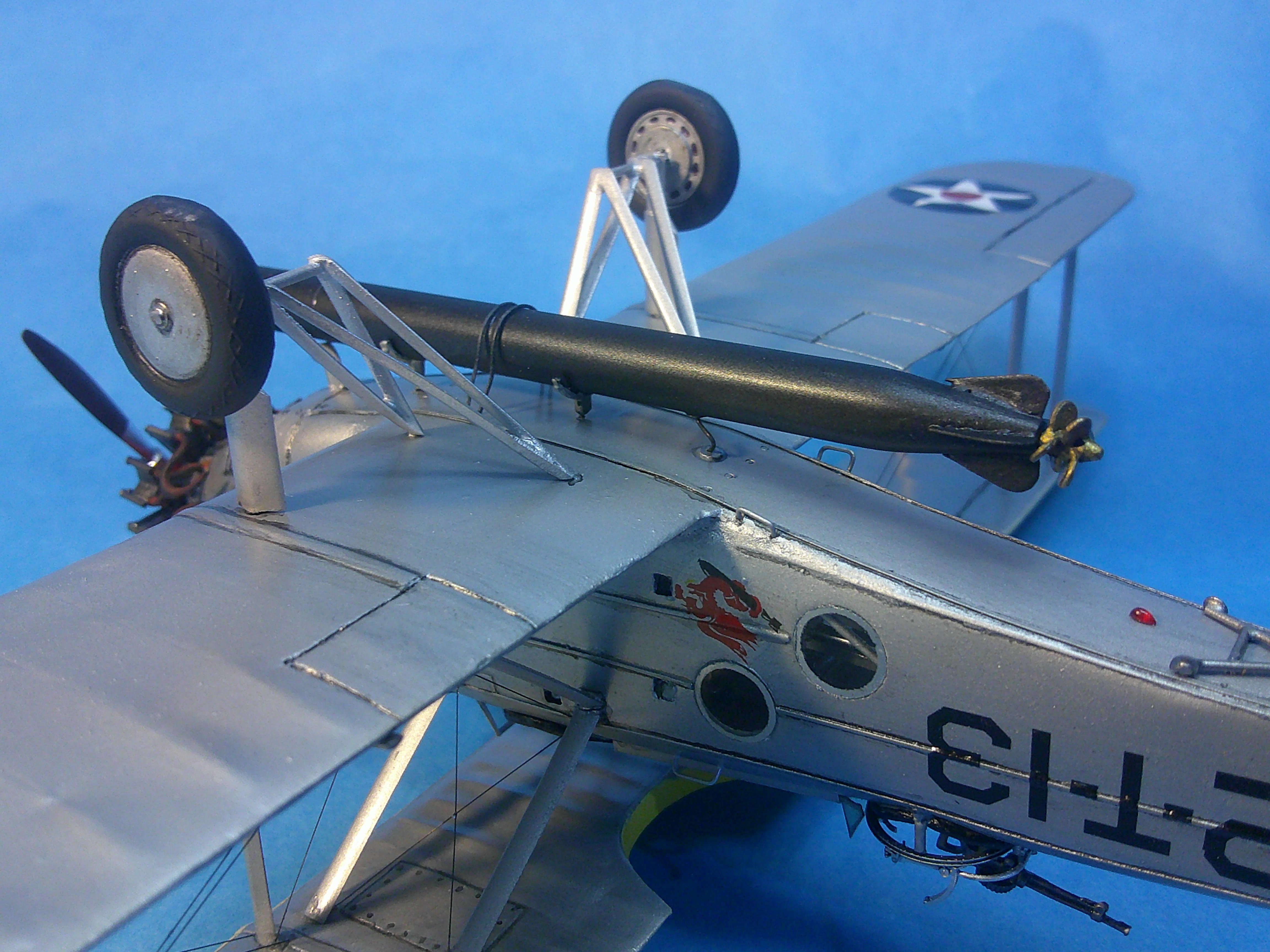
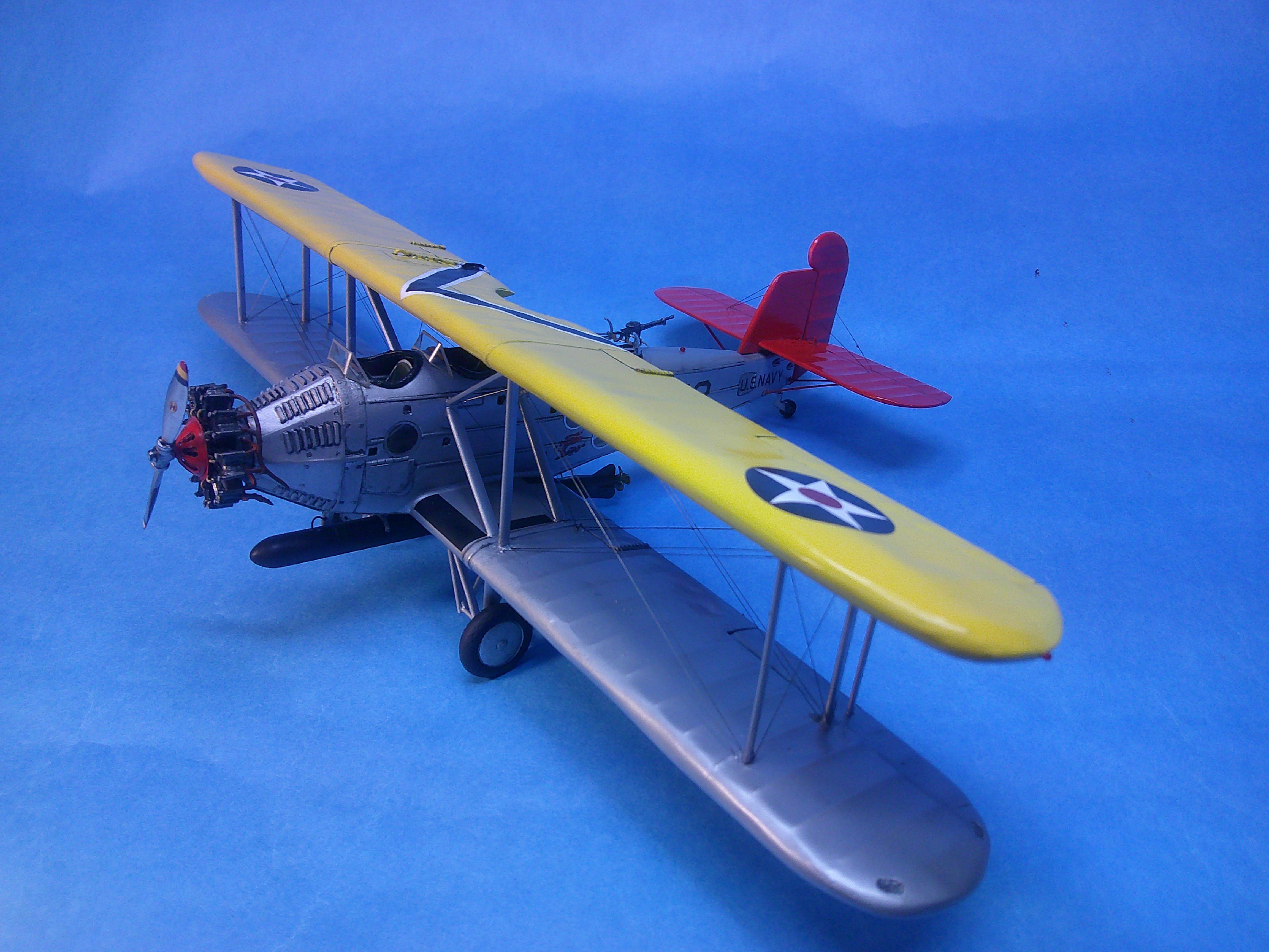
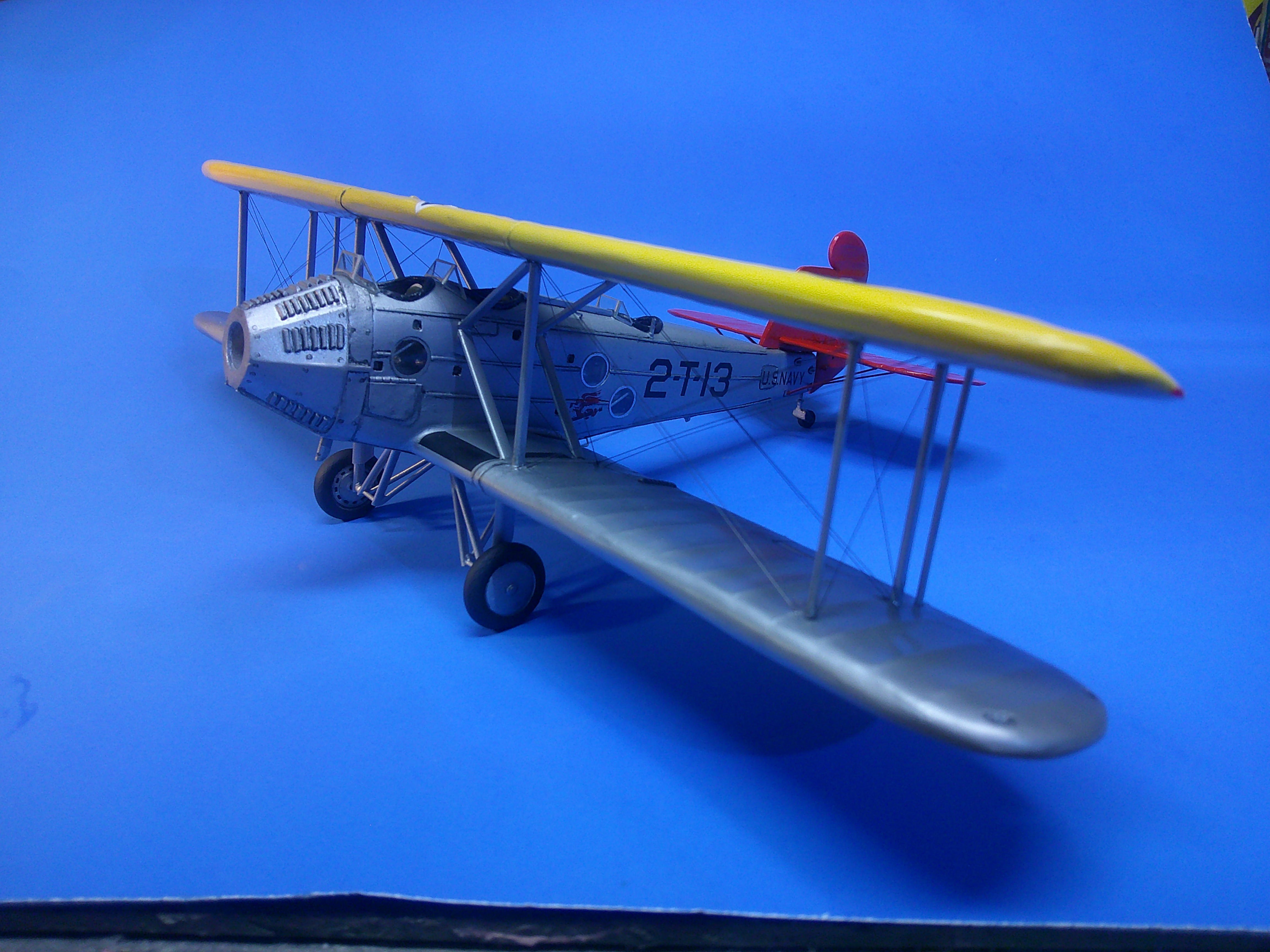
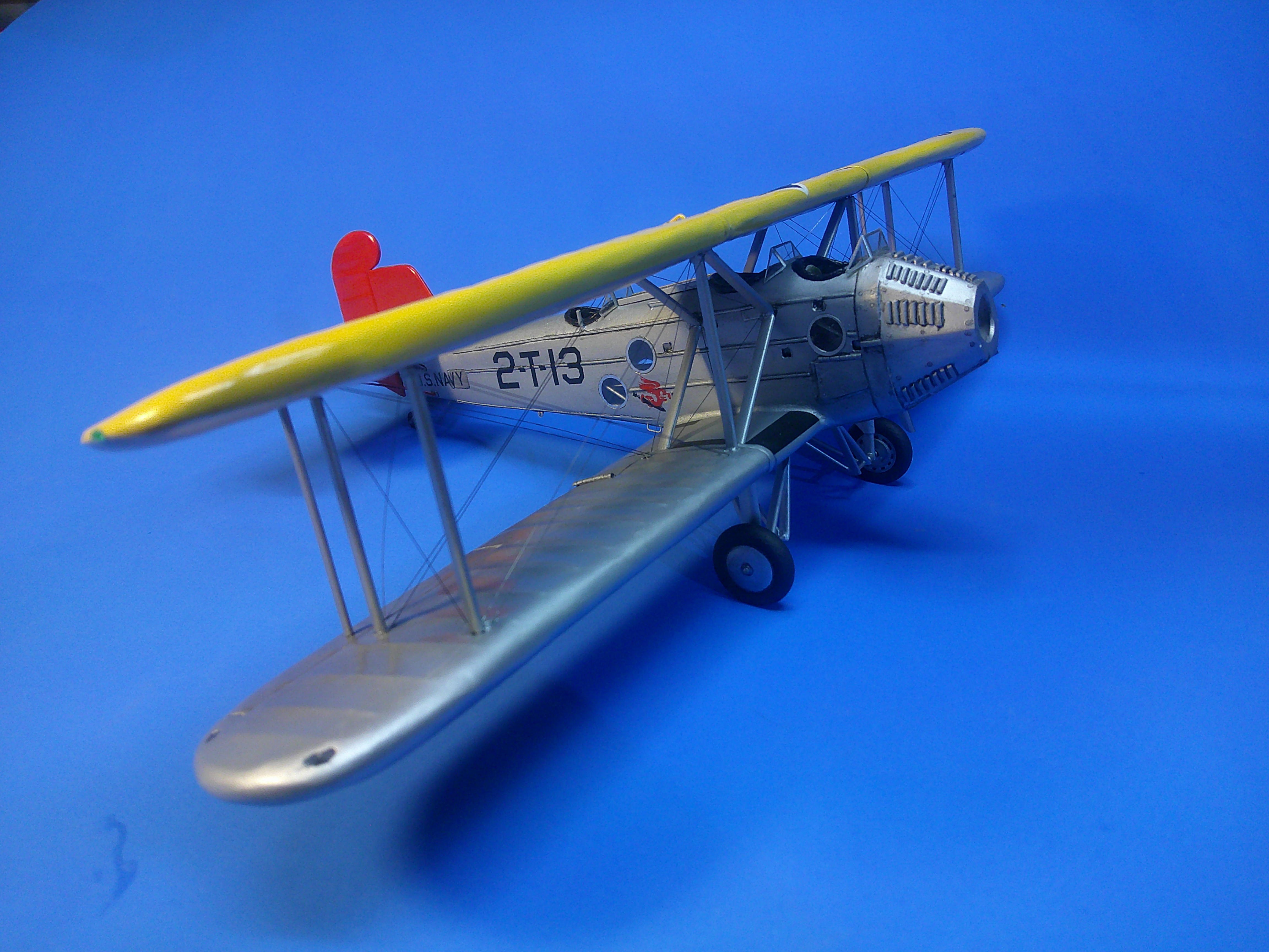
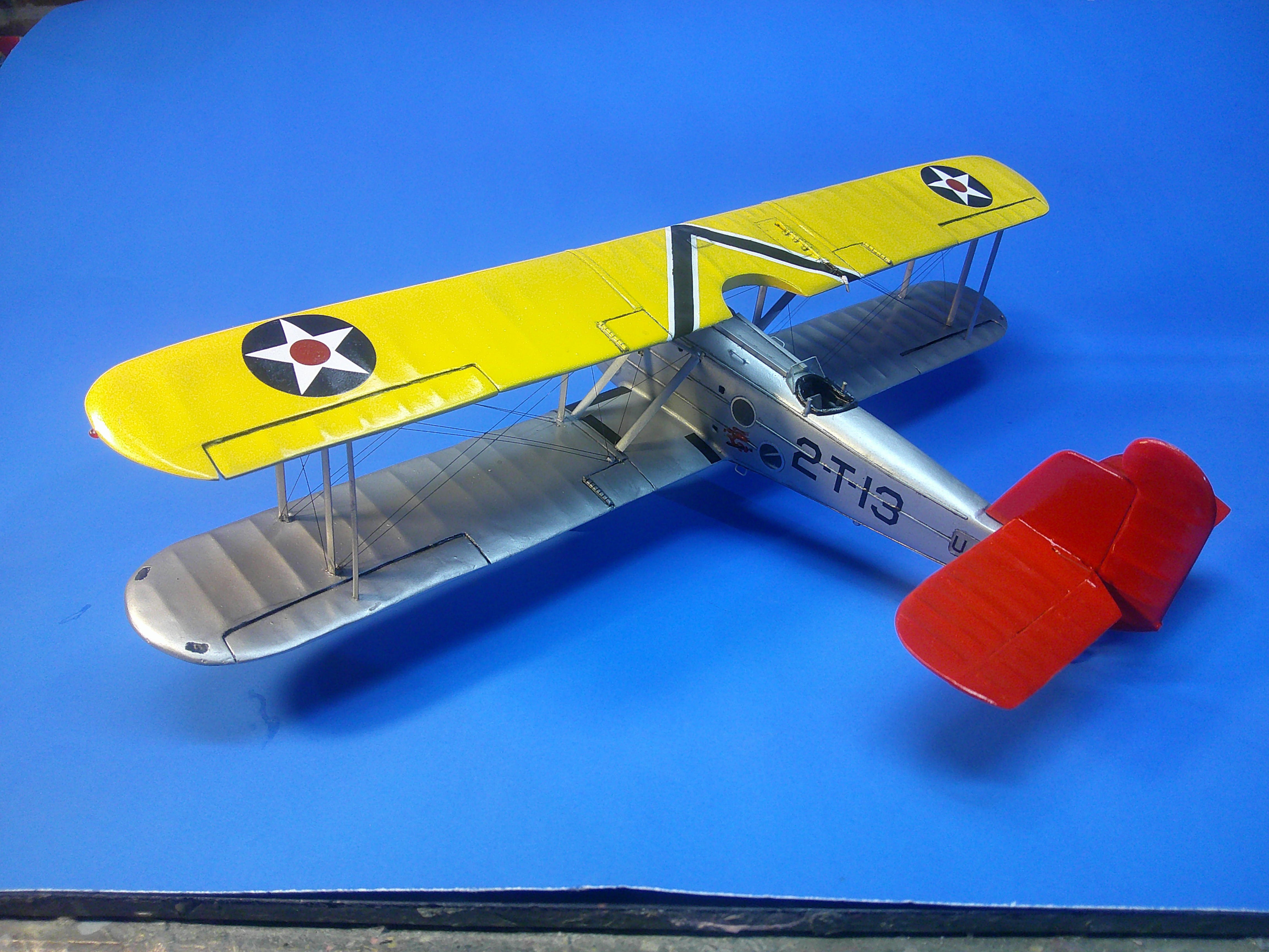
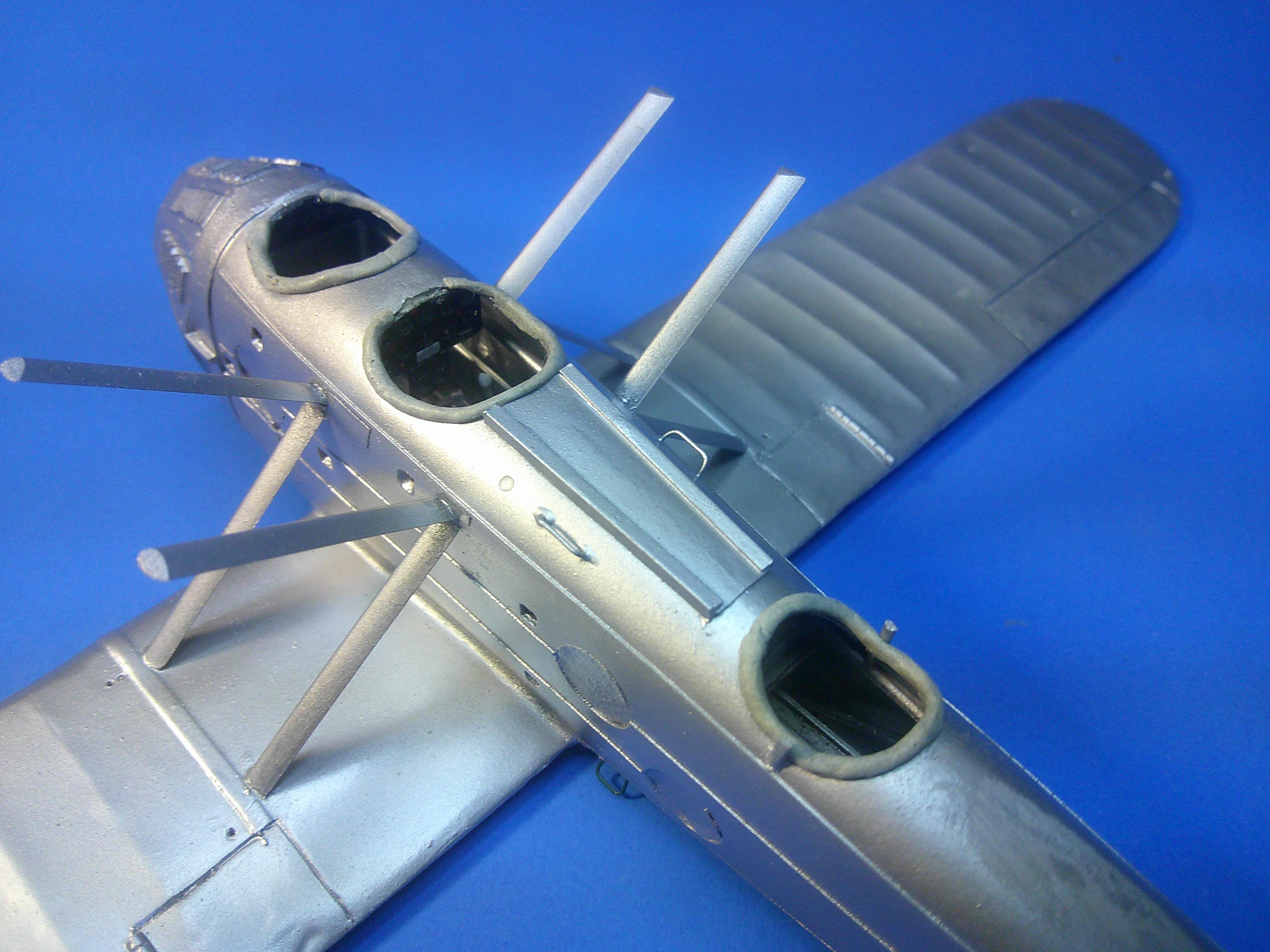
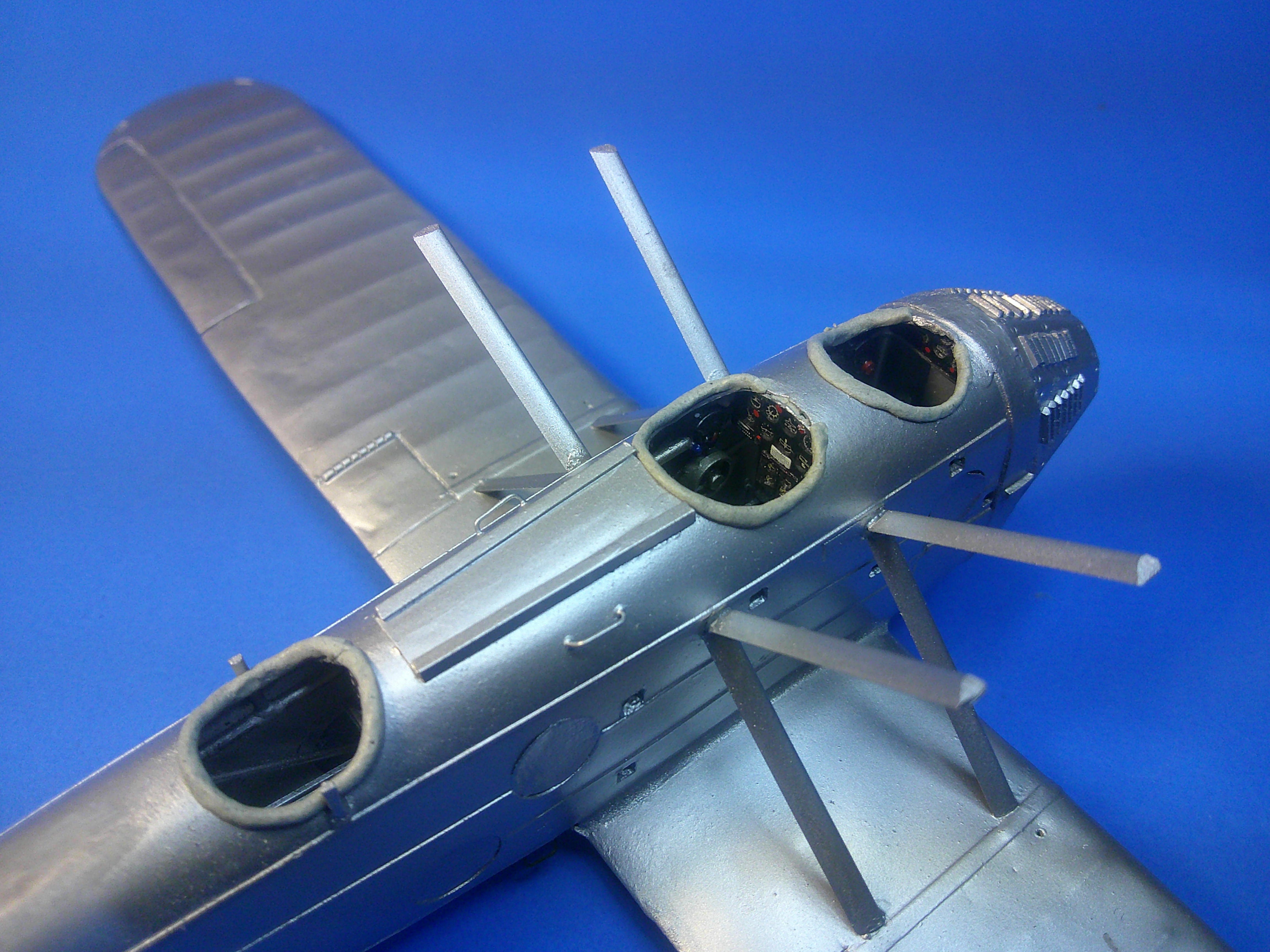
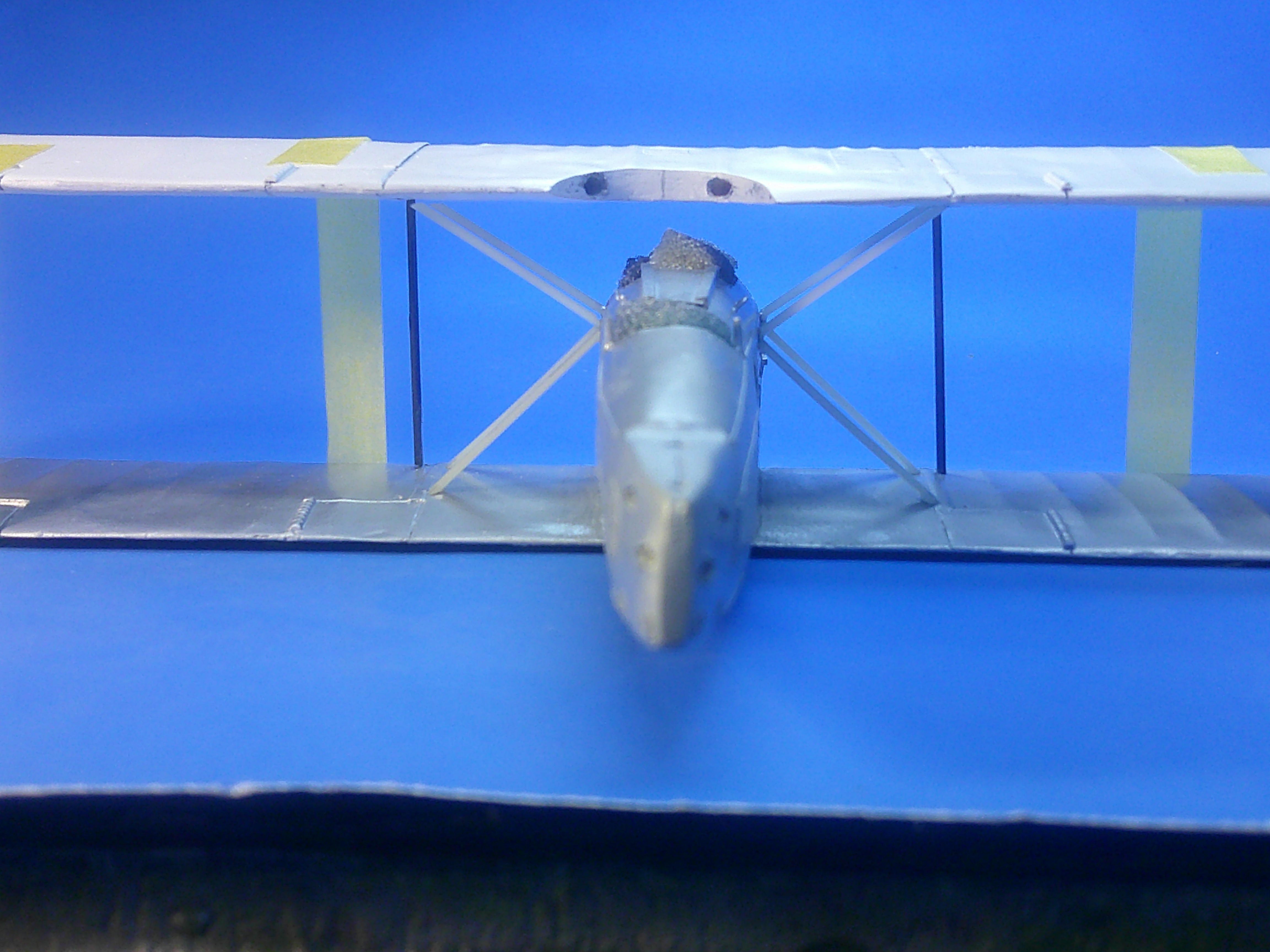
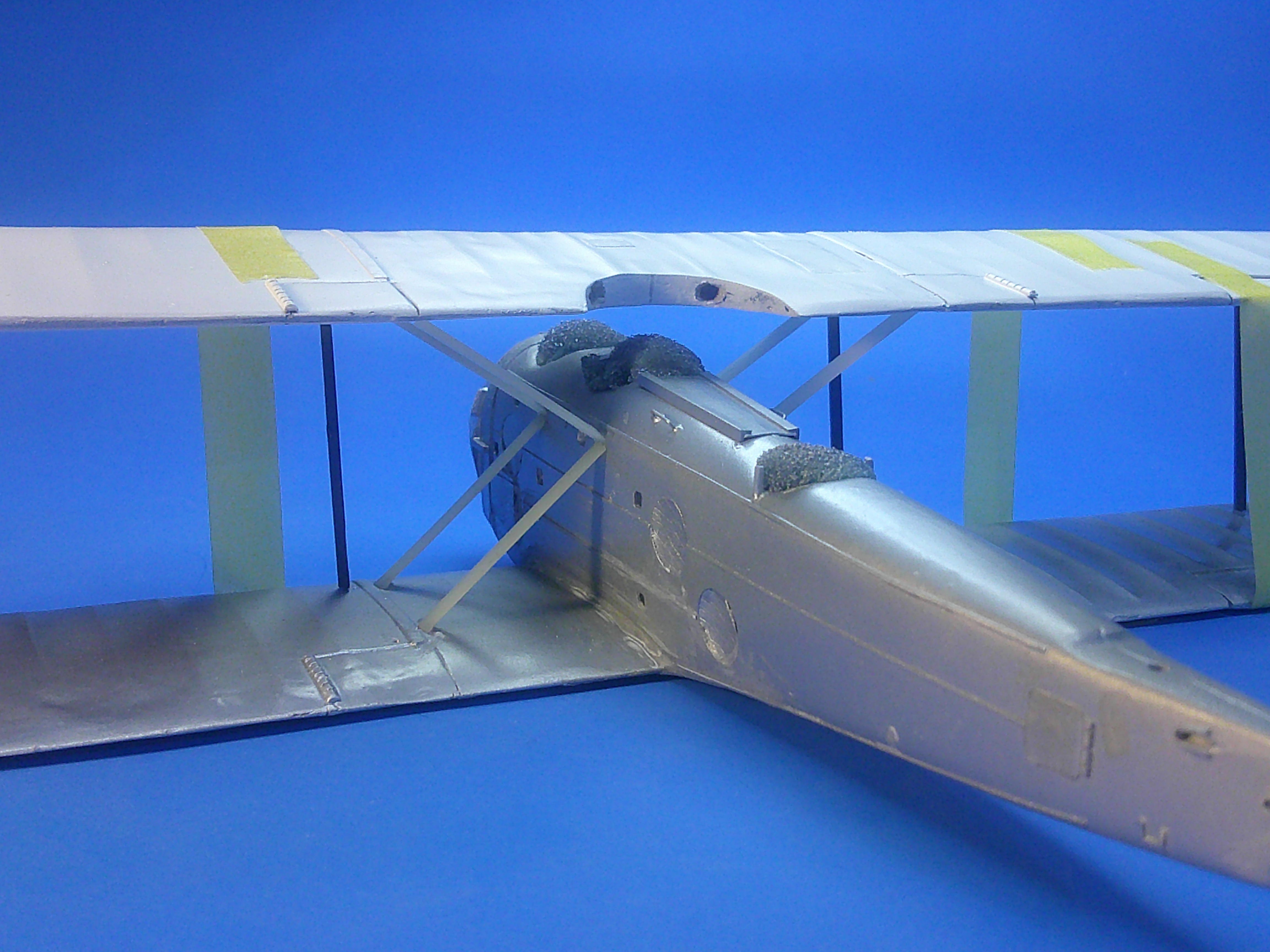
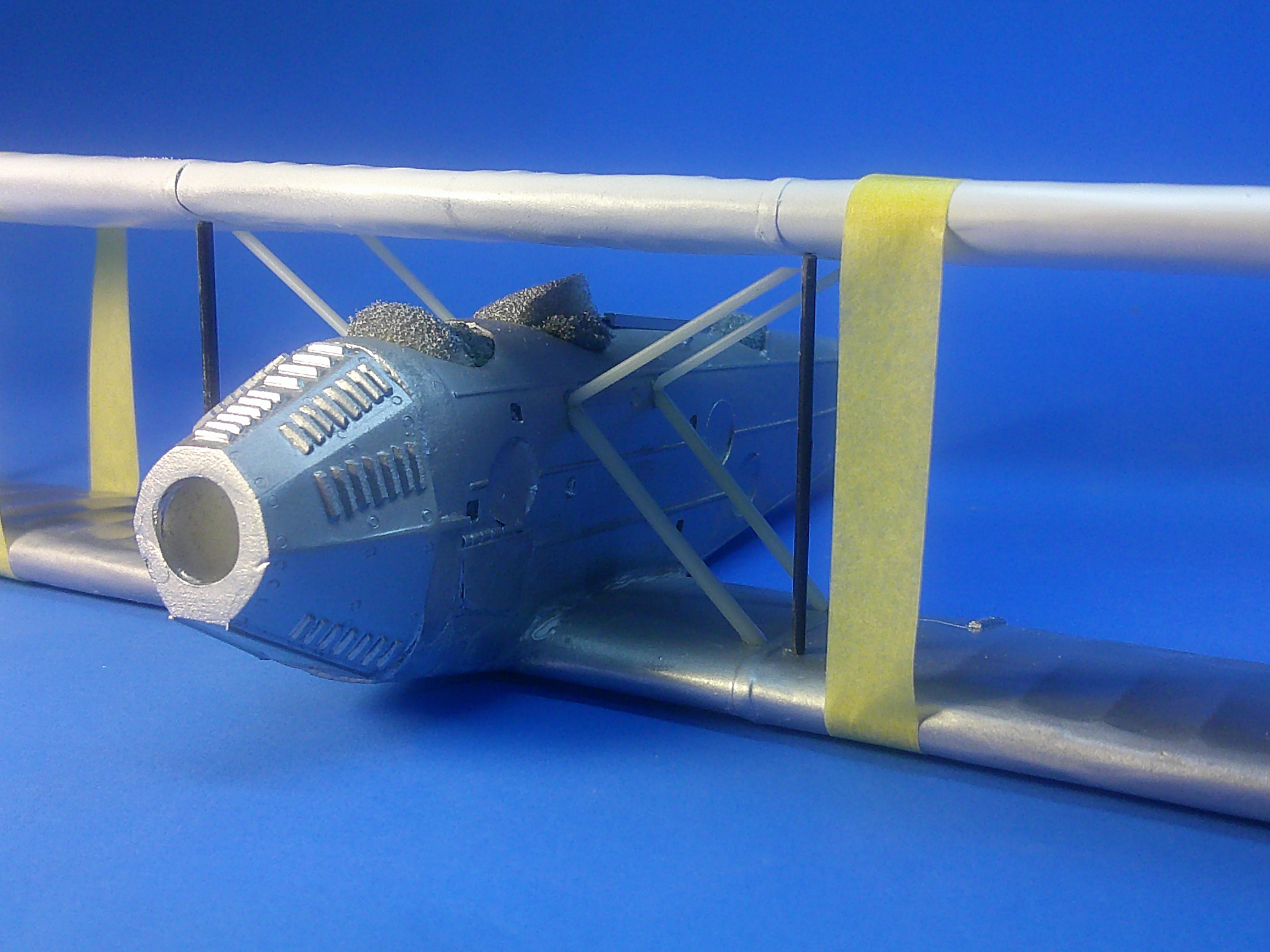
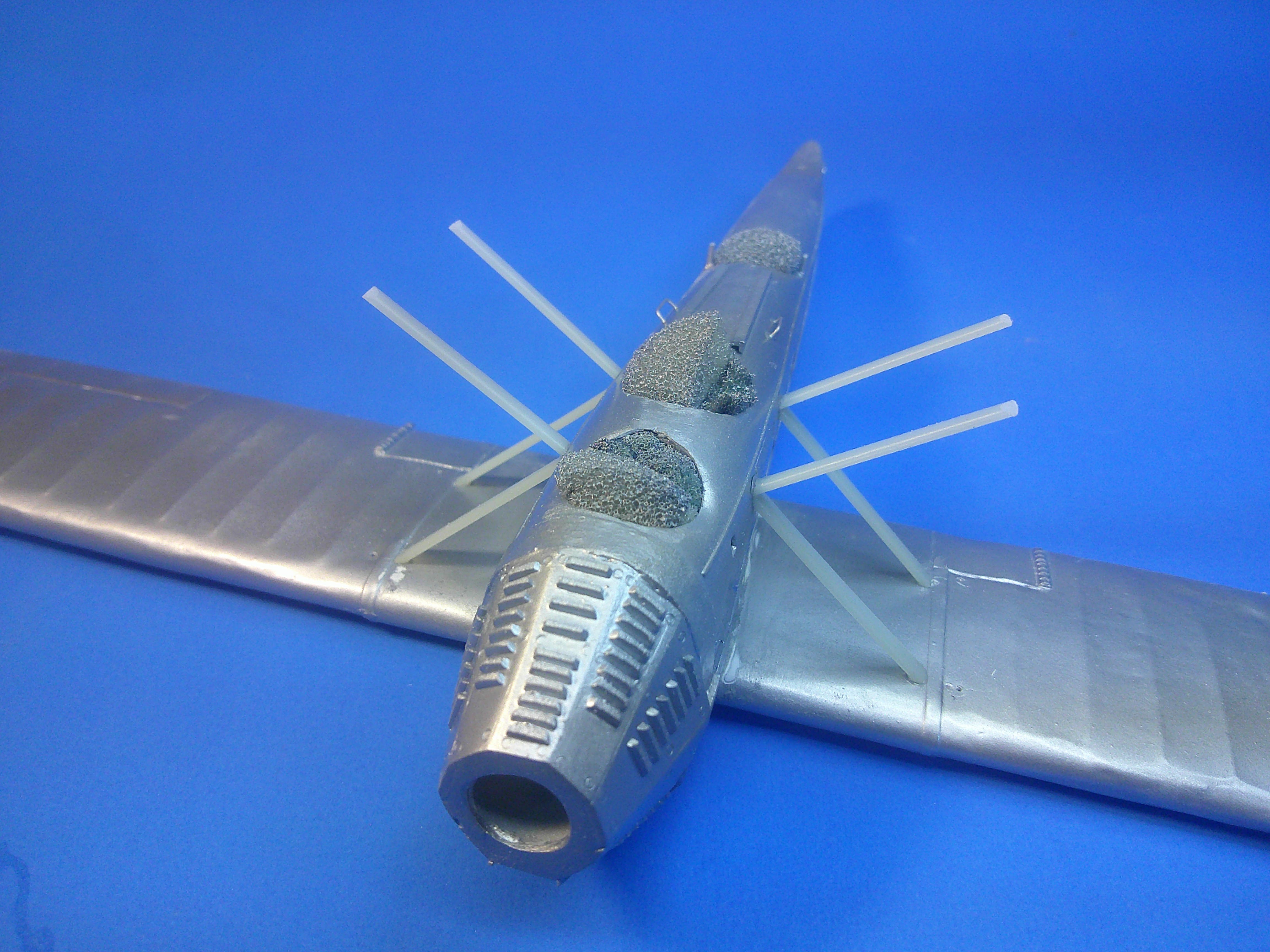
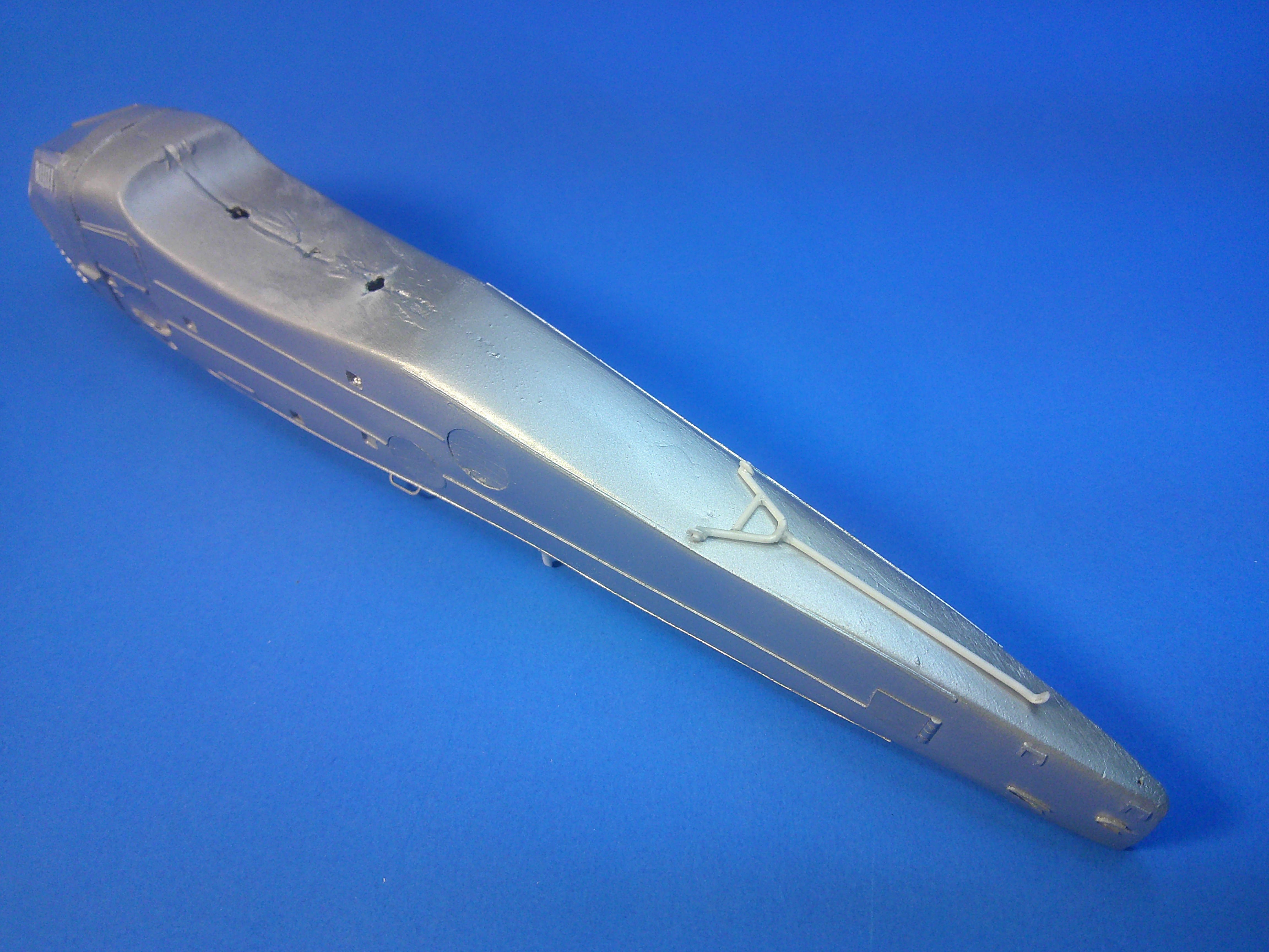
This is my 1/48 scratchbuilt Martin T4M-1 Torpedo bomber. The wings and tail surfaces are plastic wrapped balsa or plastic cores and the fuselage was vacked from a carved balsa form. Even the engine and the prop were rebuilt. The only parts not scratchbuilt were items like the main tires, the torpedo, the Scarf ring, and the Lewis gun. The complete build procedure from day-1 can be found in the "Build" topic area if you wonder what was done or how it was done. It took 3-1/2mos from start to finish. Comments, critiques, and questions are welcome, as always! feels good to have this one done! Gil

-
Calling it done! See more finished pics in the Aircraft topic area! Gil
-
Almost there....... The model is rigged except for 4 wires on the tail, the tail planes are on the model, and so are all of the wheels. The sharp eyed among you will notice there's no "T4M-1" on the vertical tail anymore. That's because the paint CRAZED after I gloss coated it! So.... it had to be stripped, sanded, and repainted and I ain't doing no more decaling! Still some "final" things to be done.... but it should be done in a day or two. More pics when she's finished! Gil
-
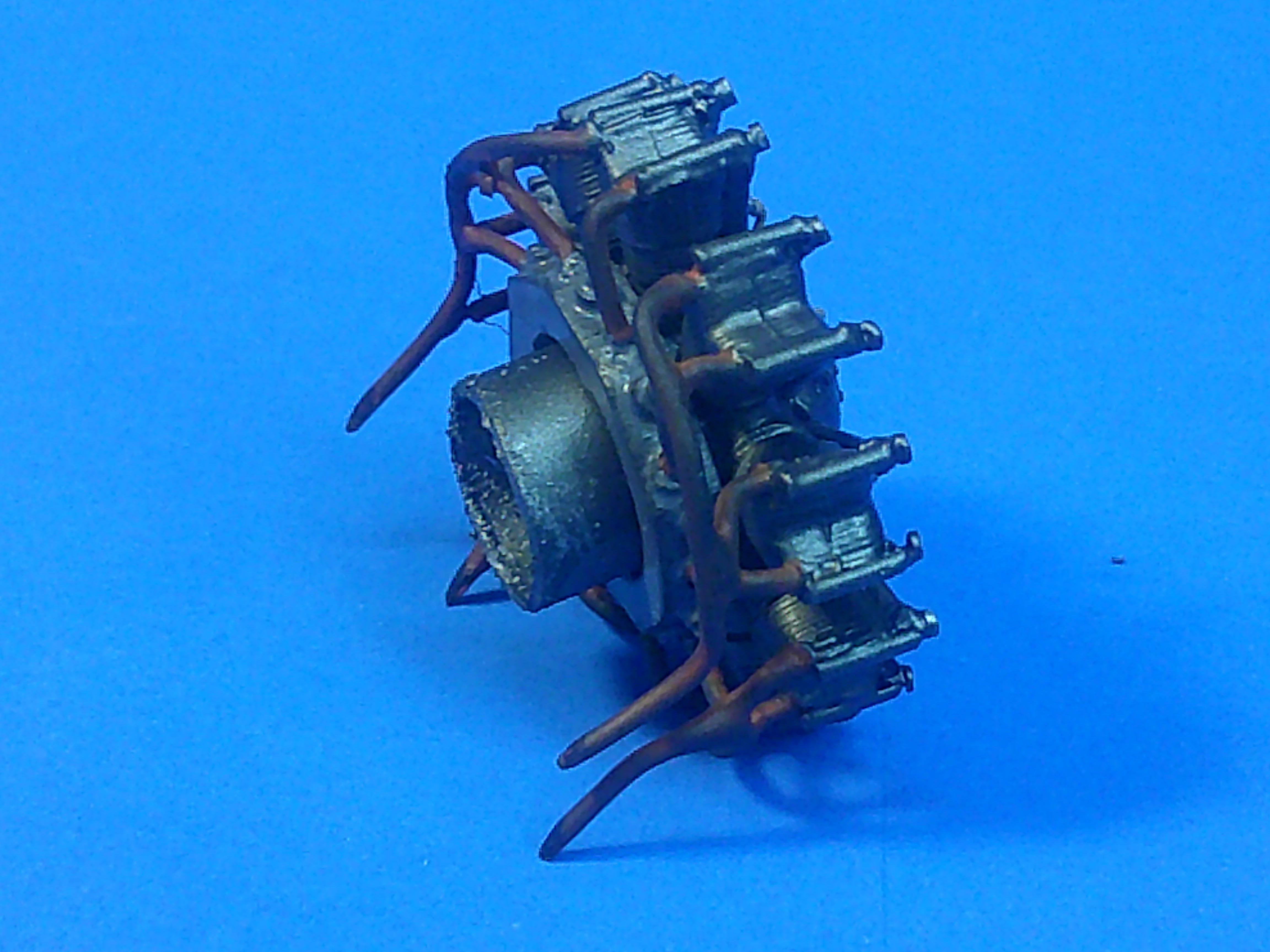
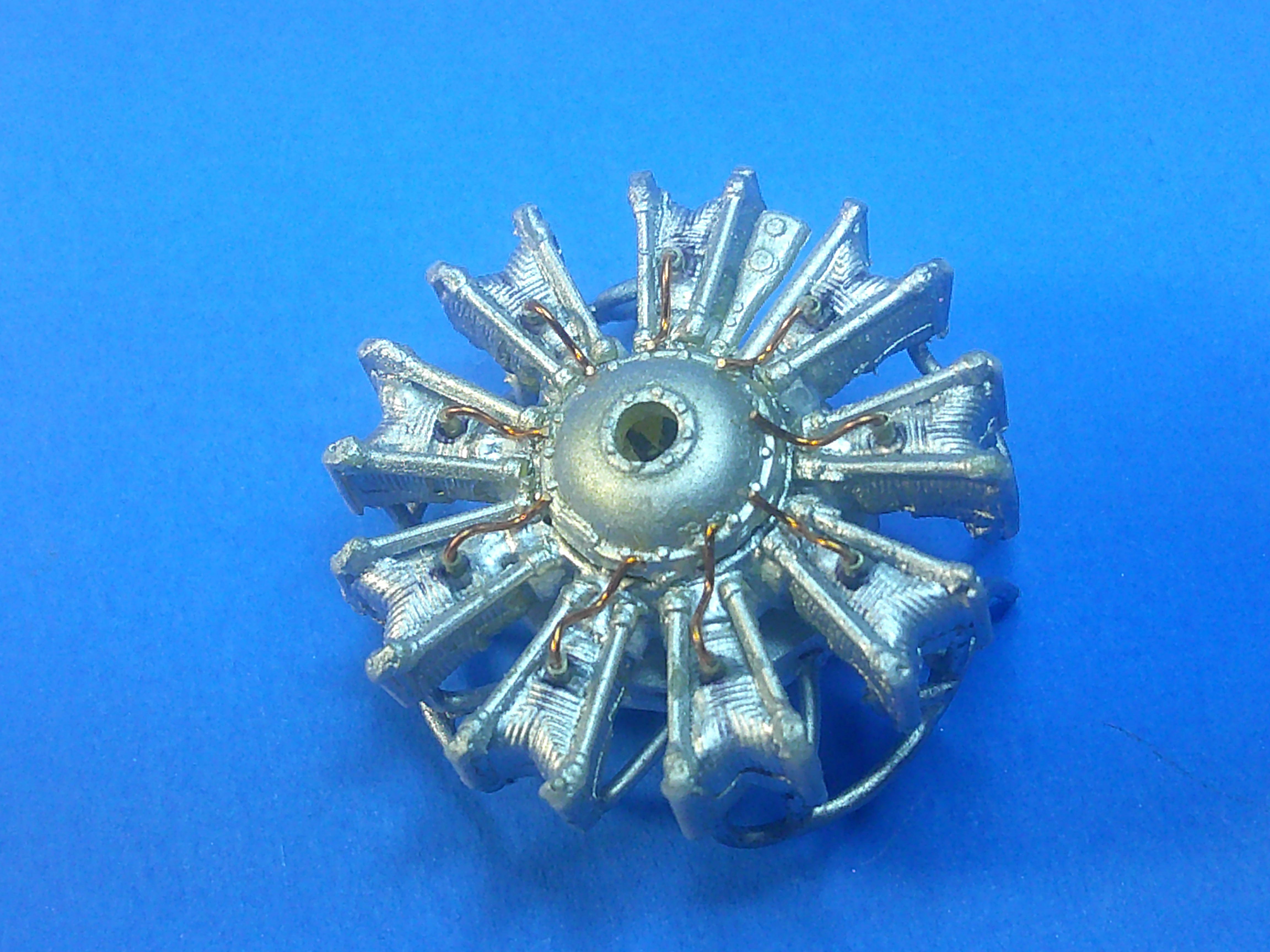
The paint and decals are all on! Just of pic of the overall progress. The black part of the chevron was painted but the white trim stripes are decals. Note the wing walks, which will need individual flat coating. The fuselage codes were cobbled together from spare decals and I was even lucky enough to have the squadron insignia in there! The "T4M-1" was added using water-slide individual letter and number decals. The dash was made by cutting a #1 in half. Pics of the painted engine front and back minus its red cooling cover. The "sealing" gloss coat is on and drying. Next up is rigging! Gil
-
I decided I needed to rebuild my control sticks into control columns.... Although references are scarce, I've seen other builds with control wheels instead of the usual "stick" for the pilot. And thusly I installed control wheels on the sticks..... The problem is THAT wouldn't actually work as turning the wheel would have no affect on a plain stick. It occurred to me I needed a control column with a mechanism that would react to the wheel movement. Again, without references, I resorted to other types from that time period which used chain drives to transmit control movements. The only problem was I had no columns nor any chains on hand.... My solution was first to make a stick post that could be sheathed in sheet plastic shapes to make a column while leaving a "channel" for the chain to sit in on each side and at the top. I also added some punched discs to imply circular control for the wheels. But how to make some "chain"? I used a ponce wheel that was run along some .005 plastic sheet (while on top of a folded paper towel for padding) 2 times to emboss the pattern seen on the piece at the far left. The thin curved piece shows how it looks if just cut apart from the sheet without coloring. I used a black marker to quickly make the pattern black, cut it thin enough to fit over the top and down the sides of each column so that (hopefully) it looks like a chain that can move with the movement of the control wheel. While this probably wouldn't work well in a larger scale I think it makes for control columns that are at least plausible as compared to the obviously implausible original stick-wheels. Anyway, that's my story and I'm sticking to it! Gil
-
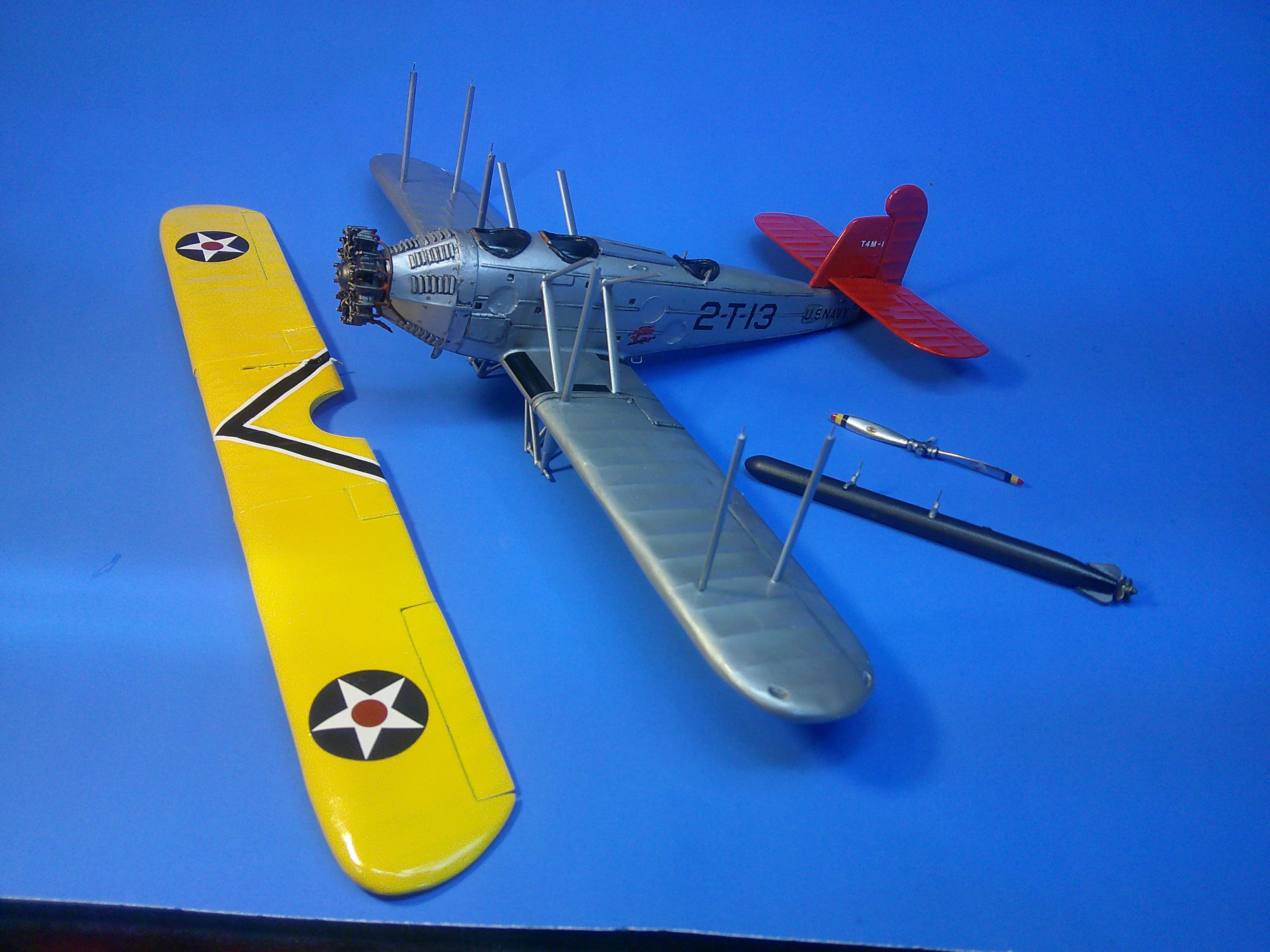
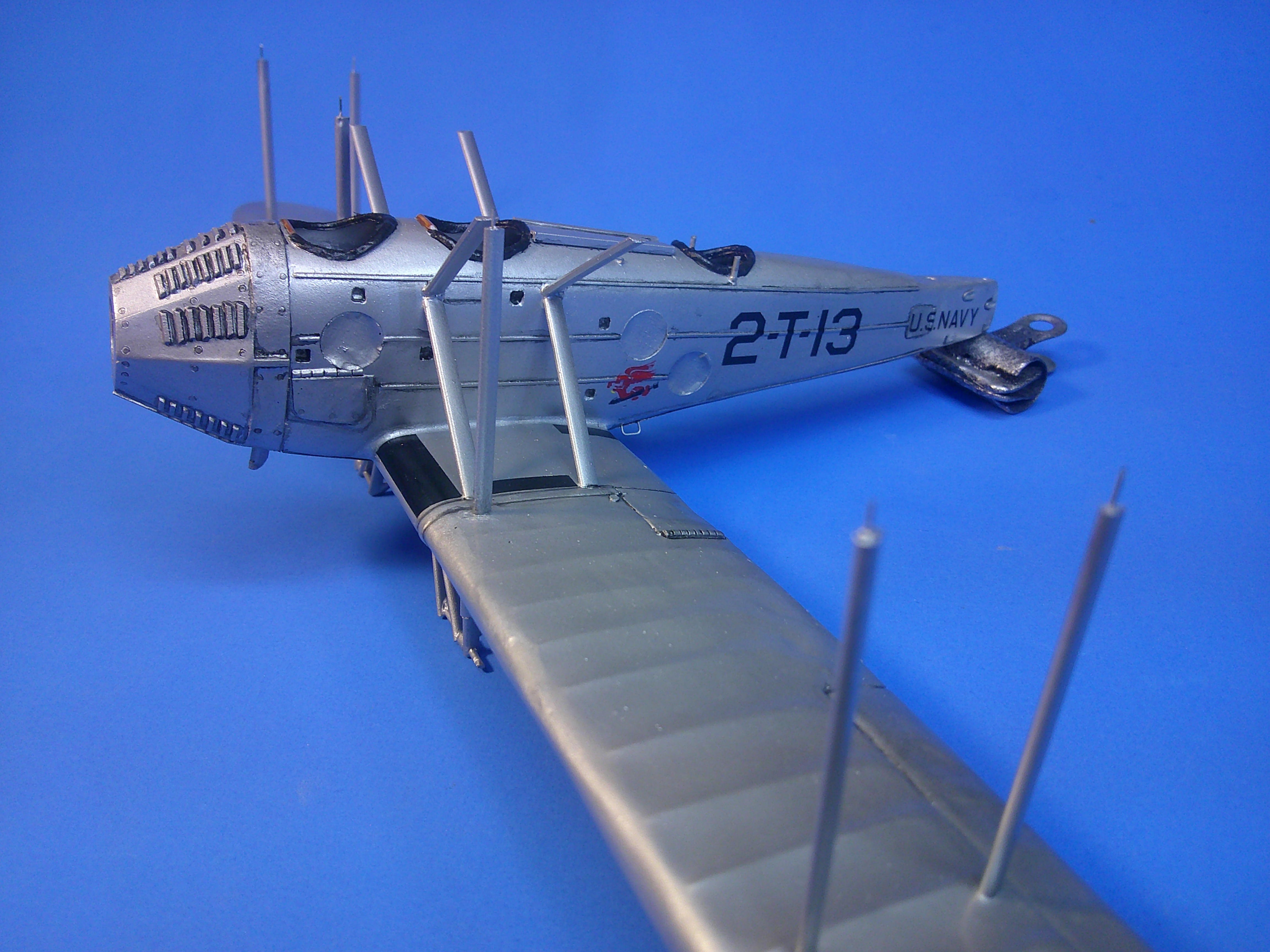
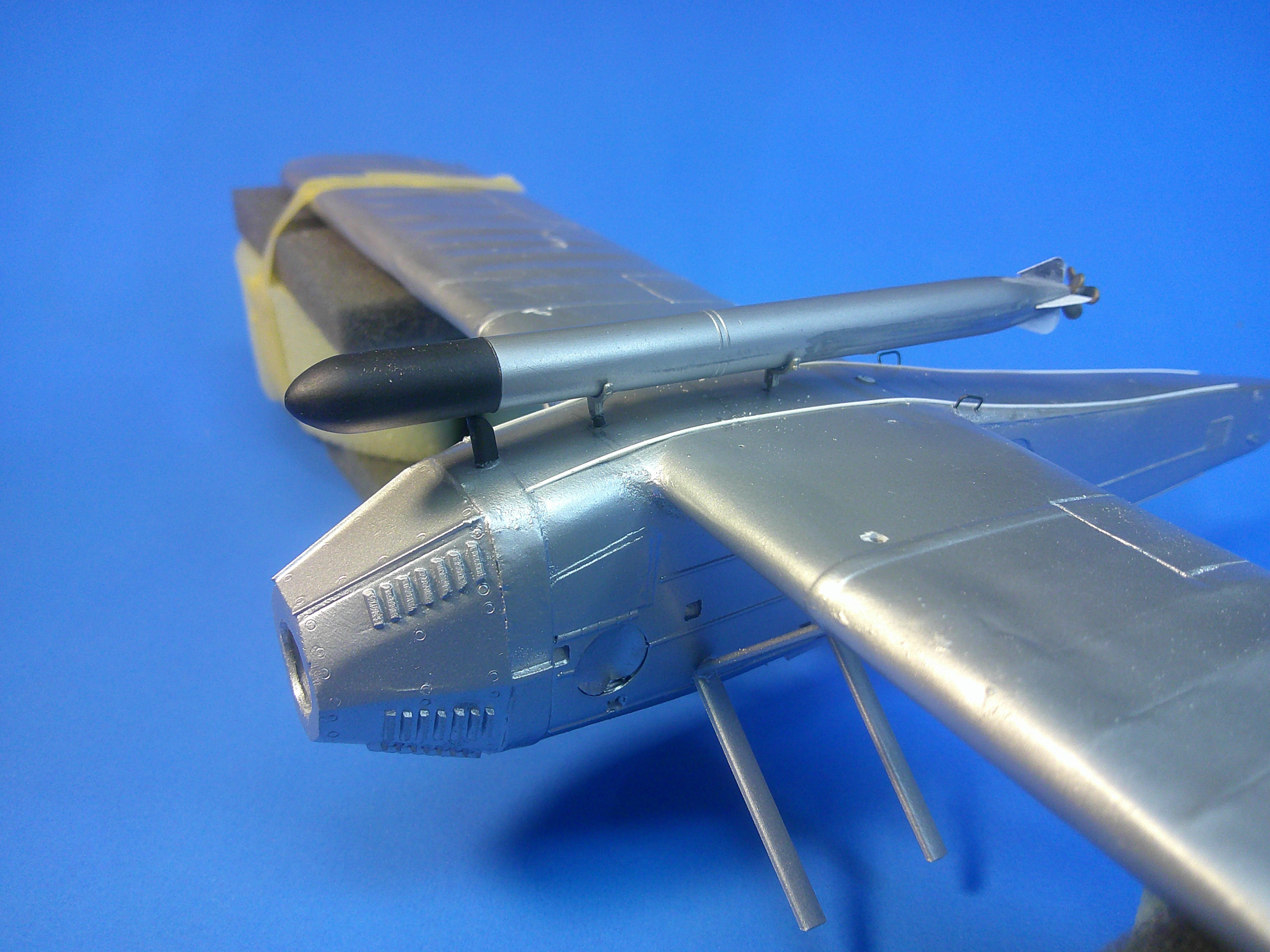
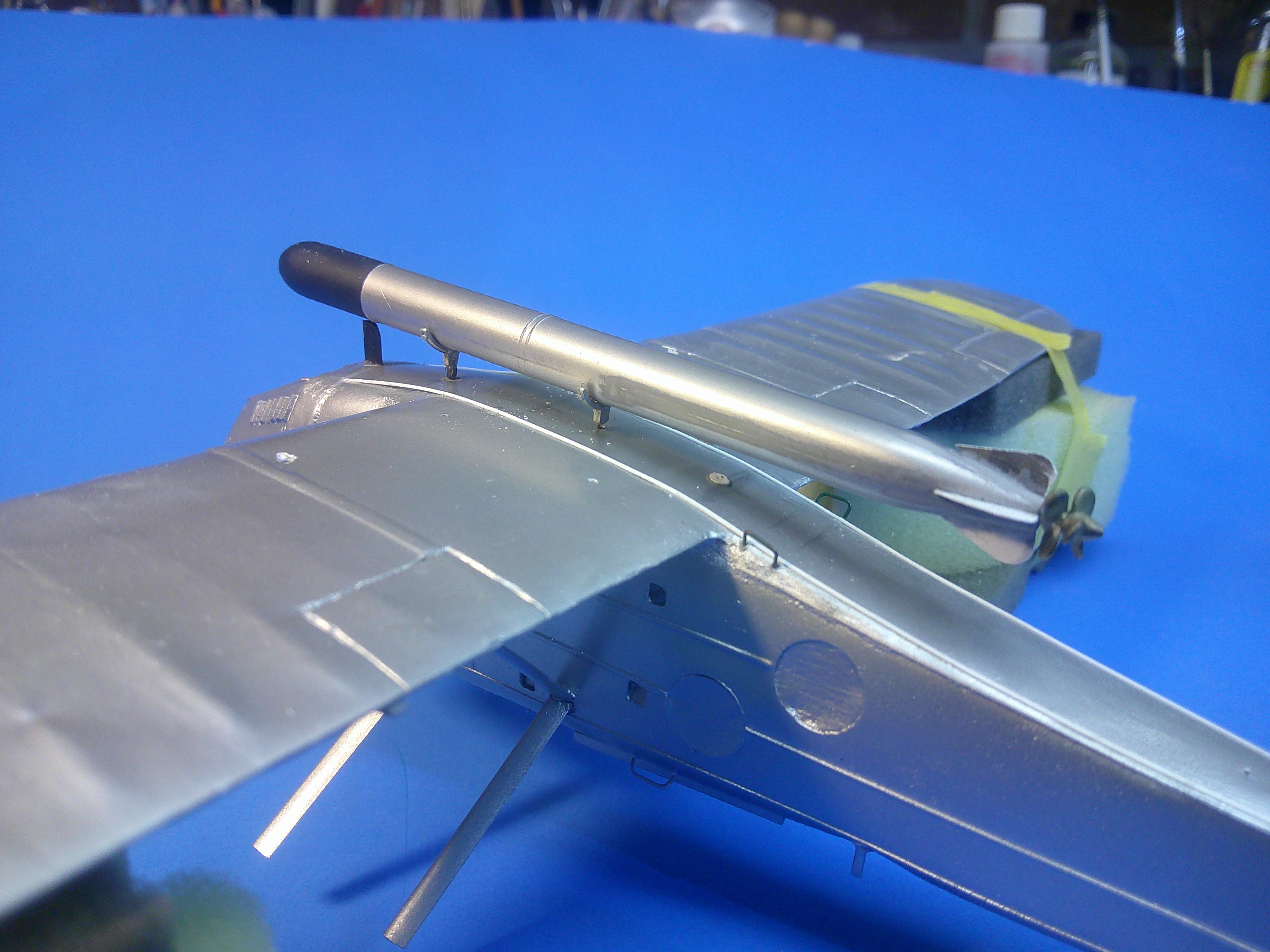
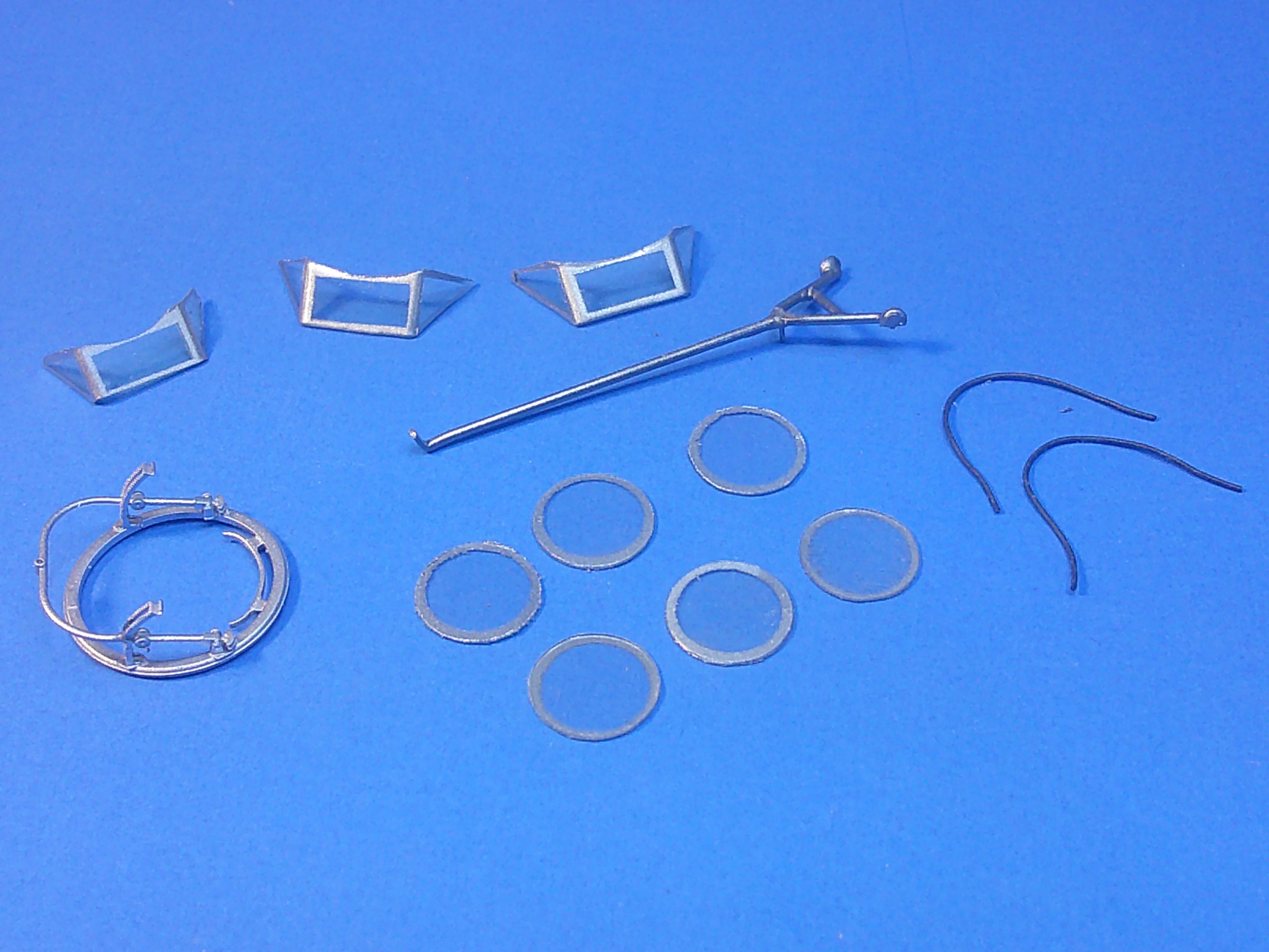
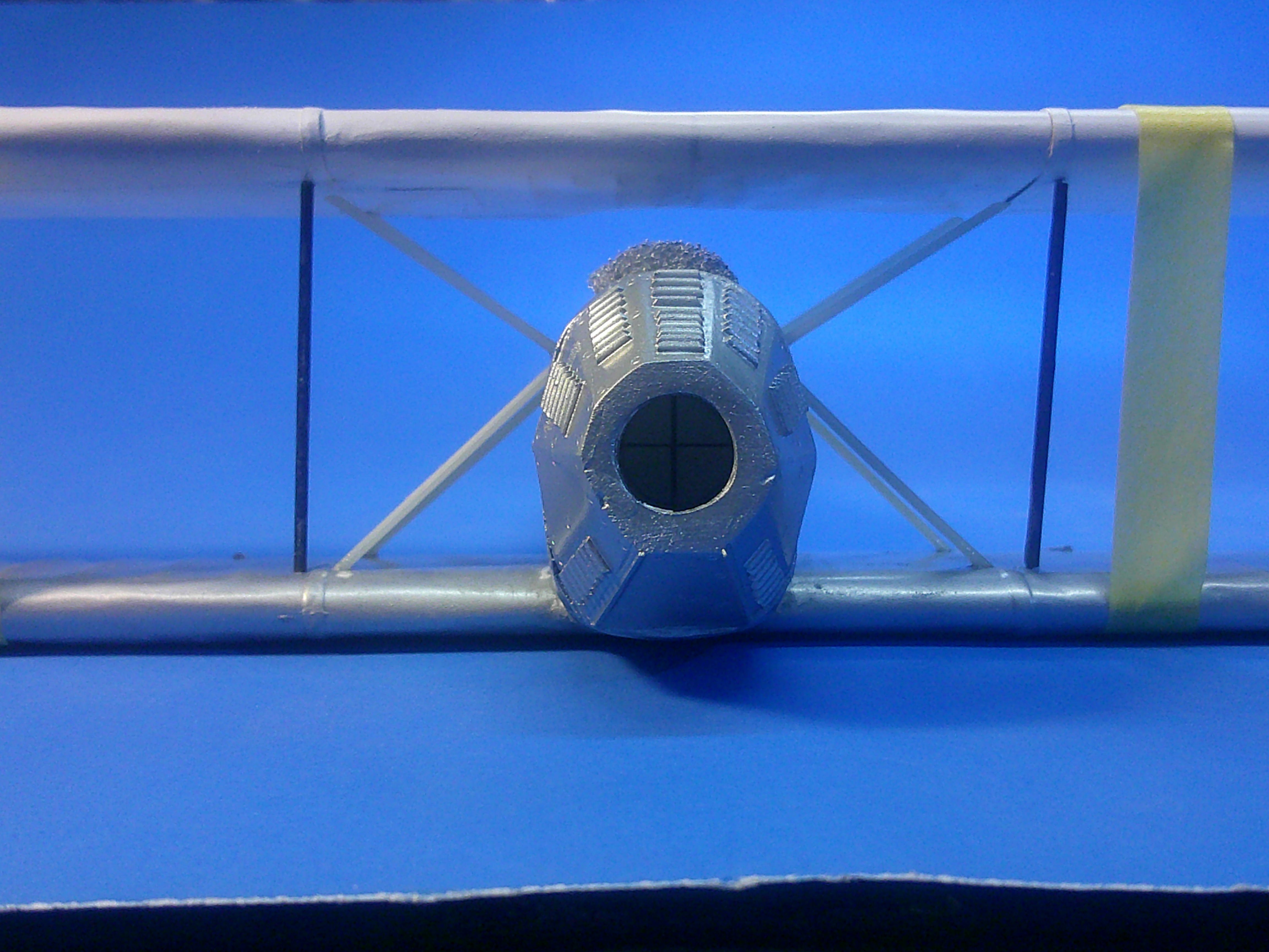
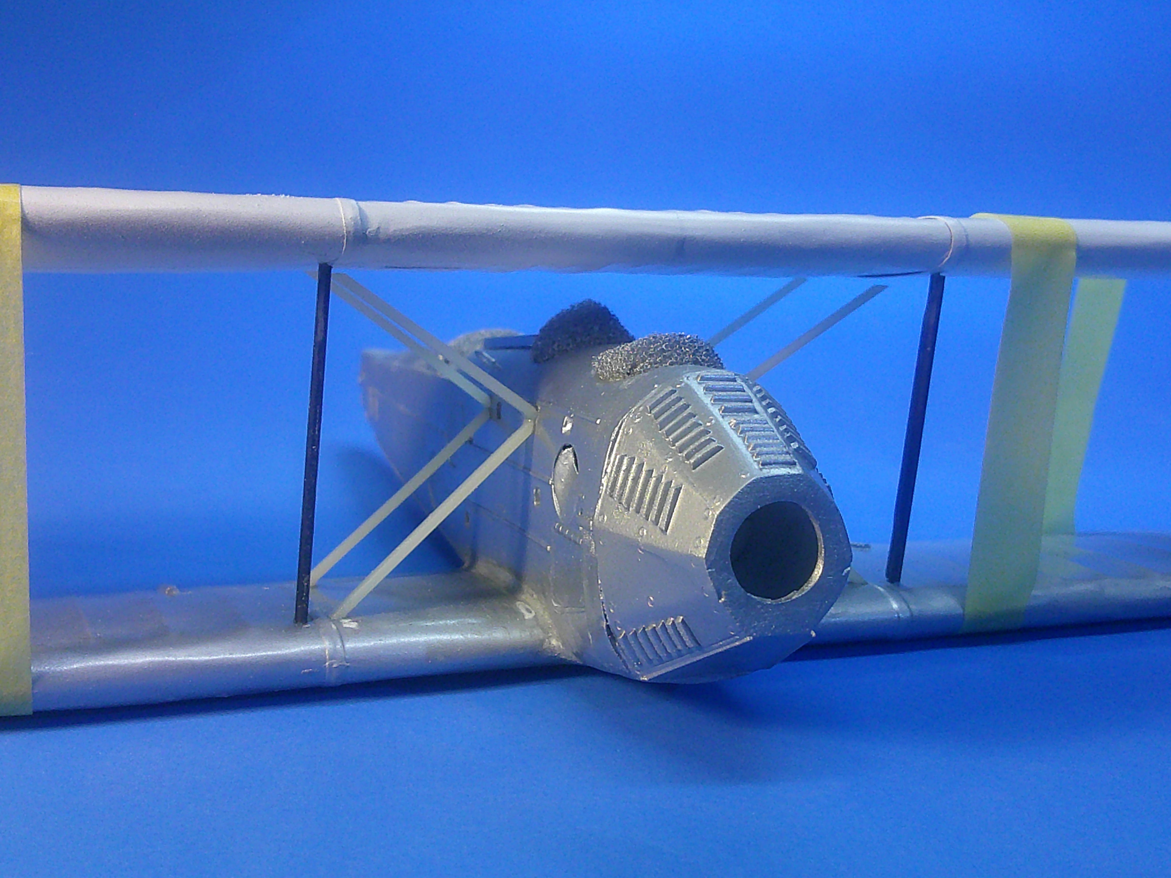
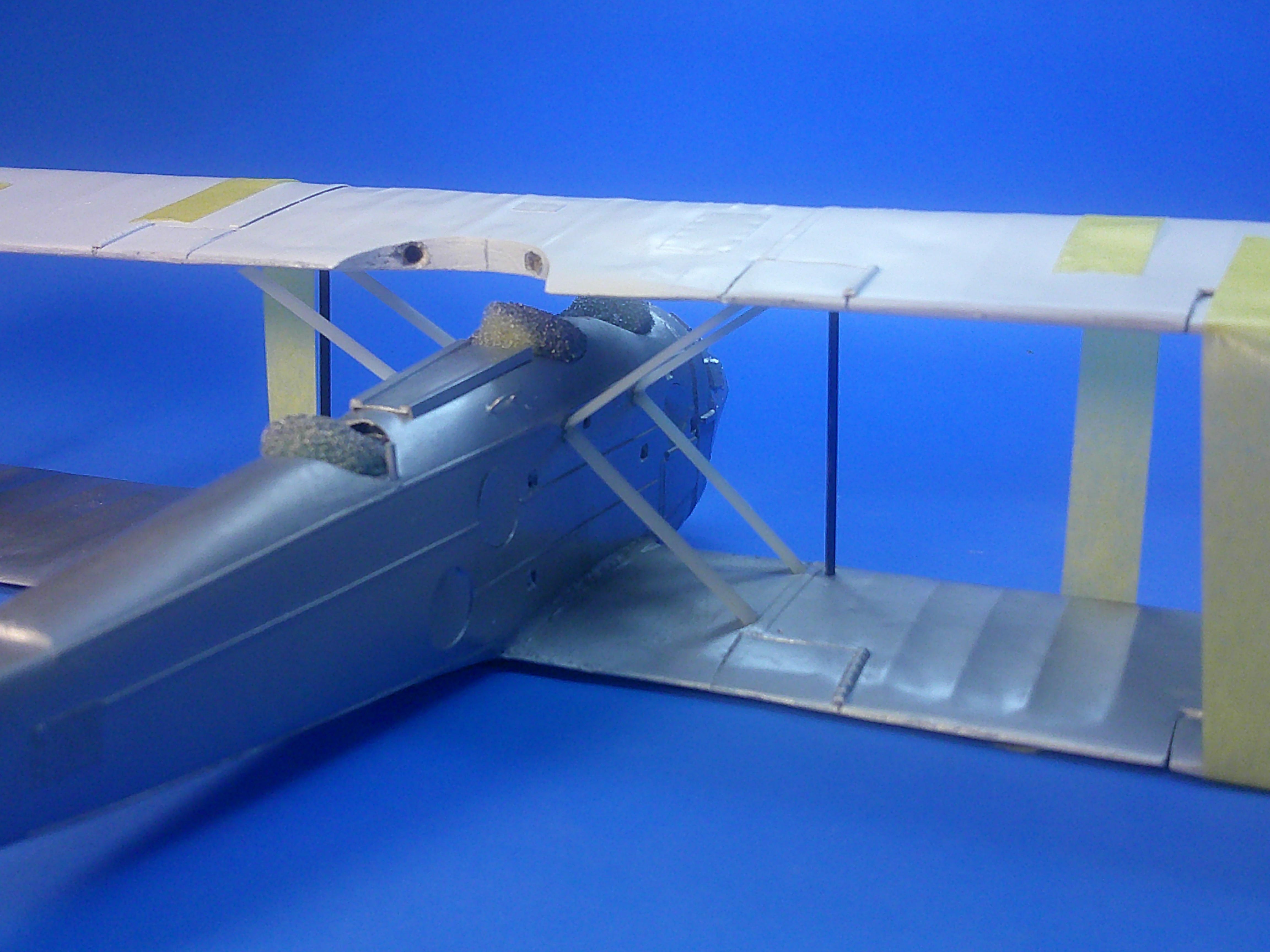
Worked on building and painting some of the fiddly bits today..... I got the side windows and the windshields masked and painted, as well as the scratchbuilt tailhook and the 3D printed Scarf ring for the Lewis gun. You can also see the wires cut to length to be used for the torpedo bracing cables. I usually use split electrical wire insulation to make coaming padding, but didn't have the right size on hand so I rolled some epoxy putty instead. I used Apoxy Sculp as it handles easily, rolling out the "ropes" on top of a paper towel and then tediously draping them around the cockpit edges. They'll be painted leather brown or black eventually. The torpedo came from the spares box, but it needed thinner fins that were more to scale so I made those from sheet plastic cut and sanded to shape. Also of note is the stack of foam padding I have taped to the wings to allow me to work on the bottom fuselage without any danger to the X struts on the fuselage. You can see the torpedo rack braces and the vertical nose stabilizer in this pic, as well as the small disc on the fuselage bottom where the electrical starter cable will exit to be attached to the torpedo. Holes were also drilled in the bottom to accommodate 2 brace cables as well. The double prop is just sitting in the torpedo for the pic and will be painted brass separately. I've also adding the last of the fuselage ribbing on the bottom edges as well as the foot step rungs. There's a few more small details that need added, but painting has begun on some of the smaller assemblies and I think I'm close to starting to paint the top wing yellow! At least it feels like things are finally starting to come together! Gil
-
Holy cow what a contraption! Since I see no means of propulsion I'm guessing it was a glider? Very cool and unique build! Gil
-
The final support struts have been added! The top struts are not cemented to the top wing yet! I'll have to be careful handling it from now on as those struts are glued, but not pinned! Yet another major step and what should be the last "major" components needed for the build. Gil
-
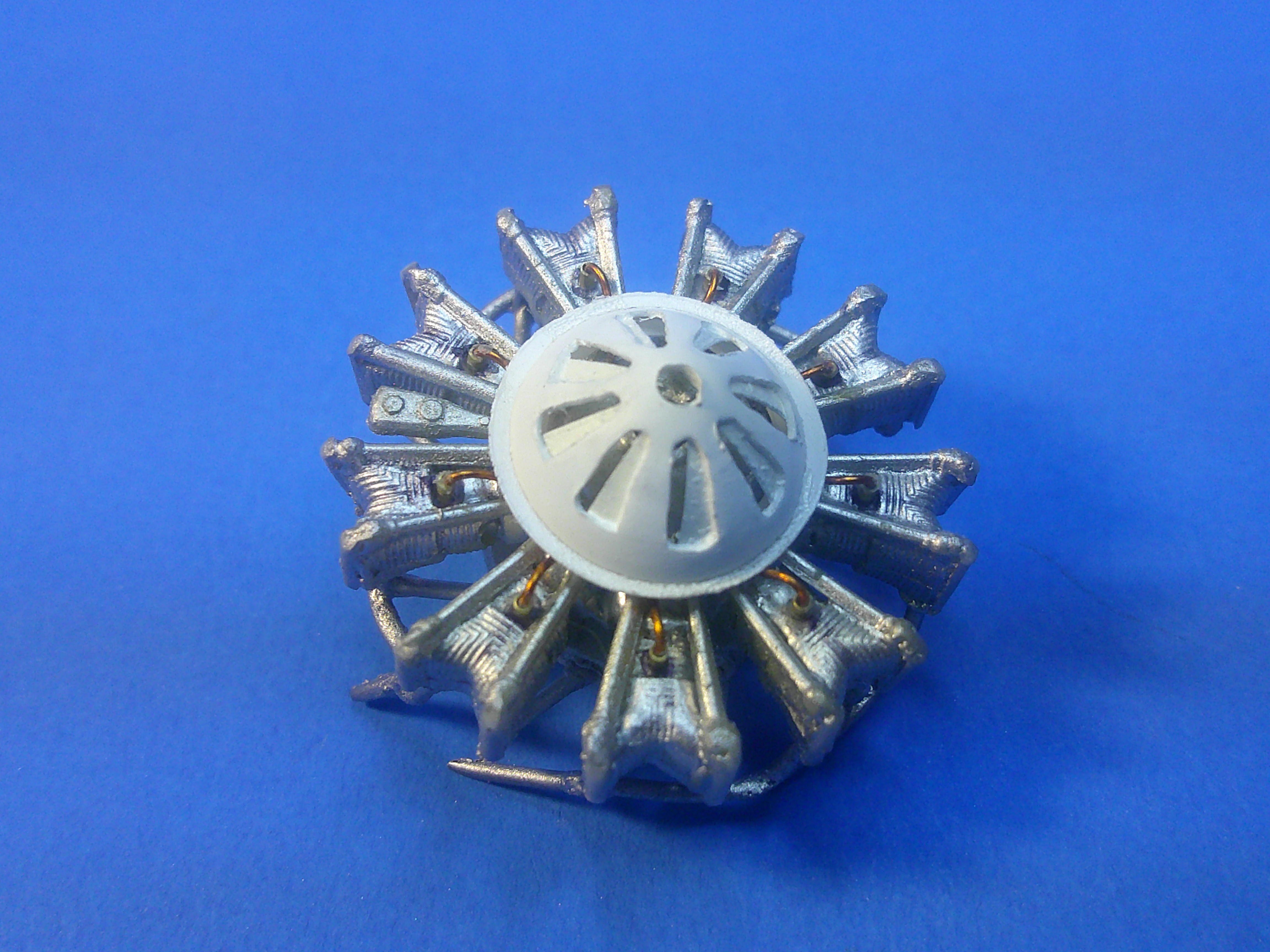
Got the engine plugged and wired..... As you can see the oil cooler cover covers a multitude of sins of omission around the crankcase! Gil
-
That's the nice thing about solder wire..... it bends easily but also holds the shape well. Glue one end into a socket hole, bend, apply a dab of superglue at the next juncture, and keep going from there. It was tedious, but not too taxing from a "holding" standpoint. Gil
-
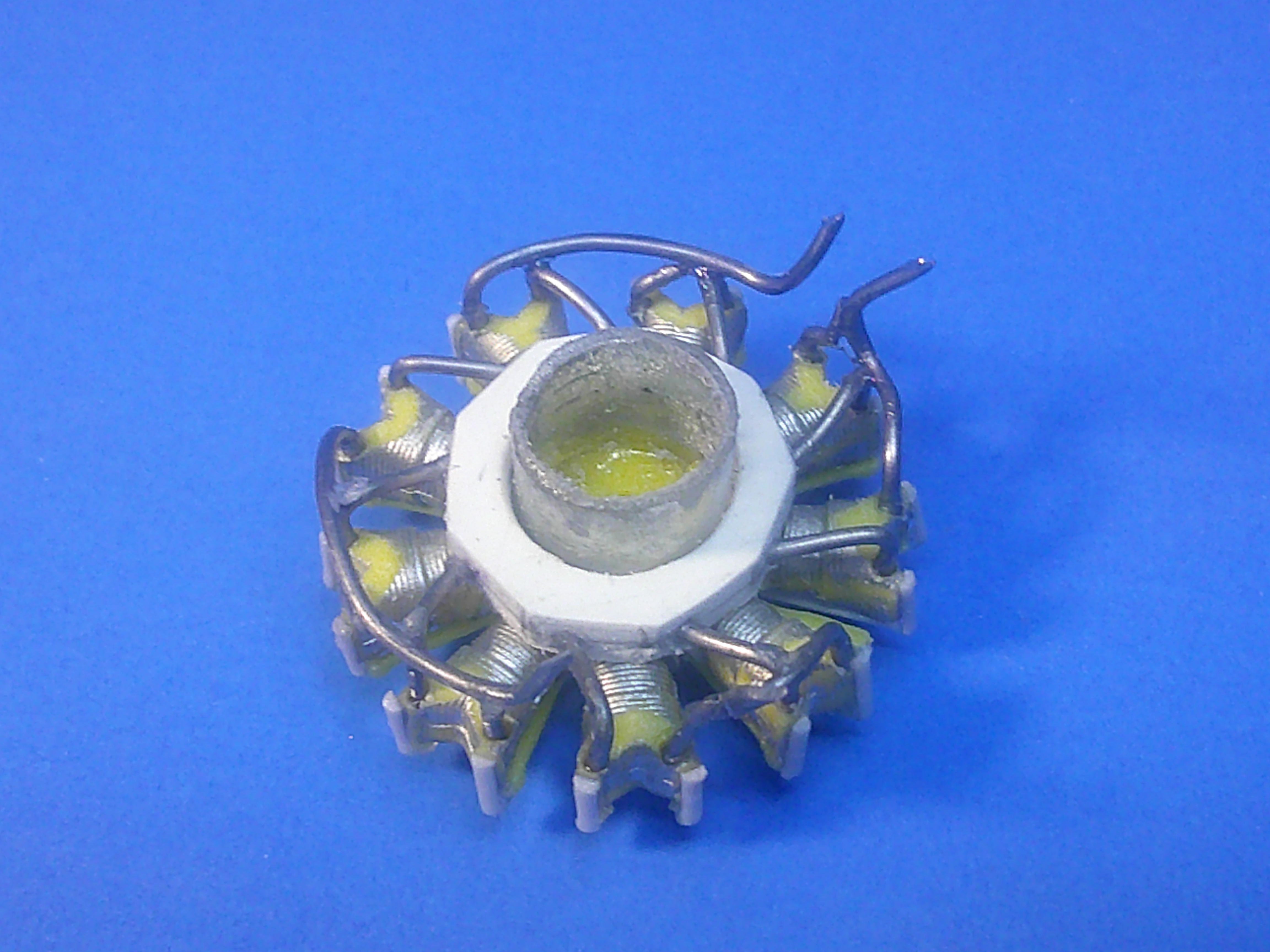
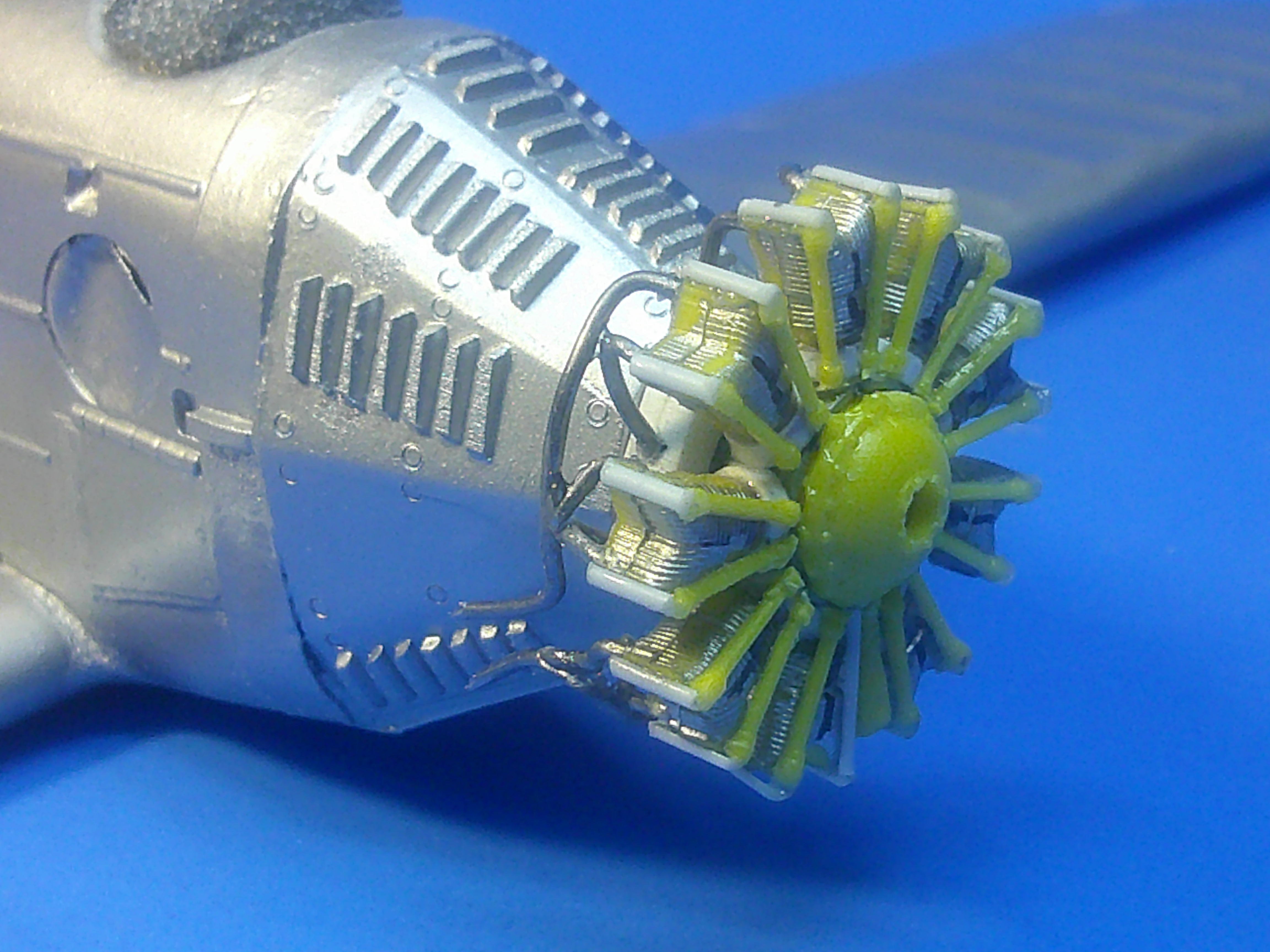
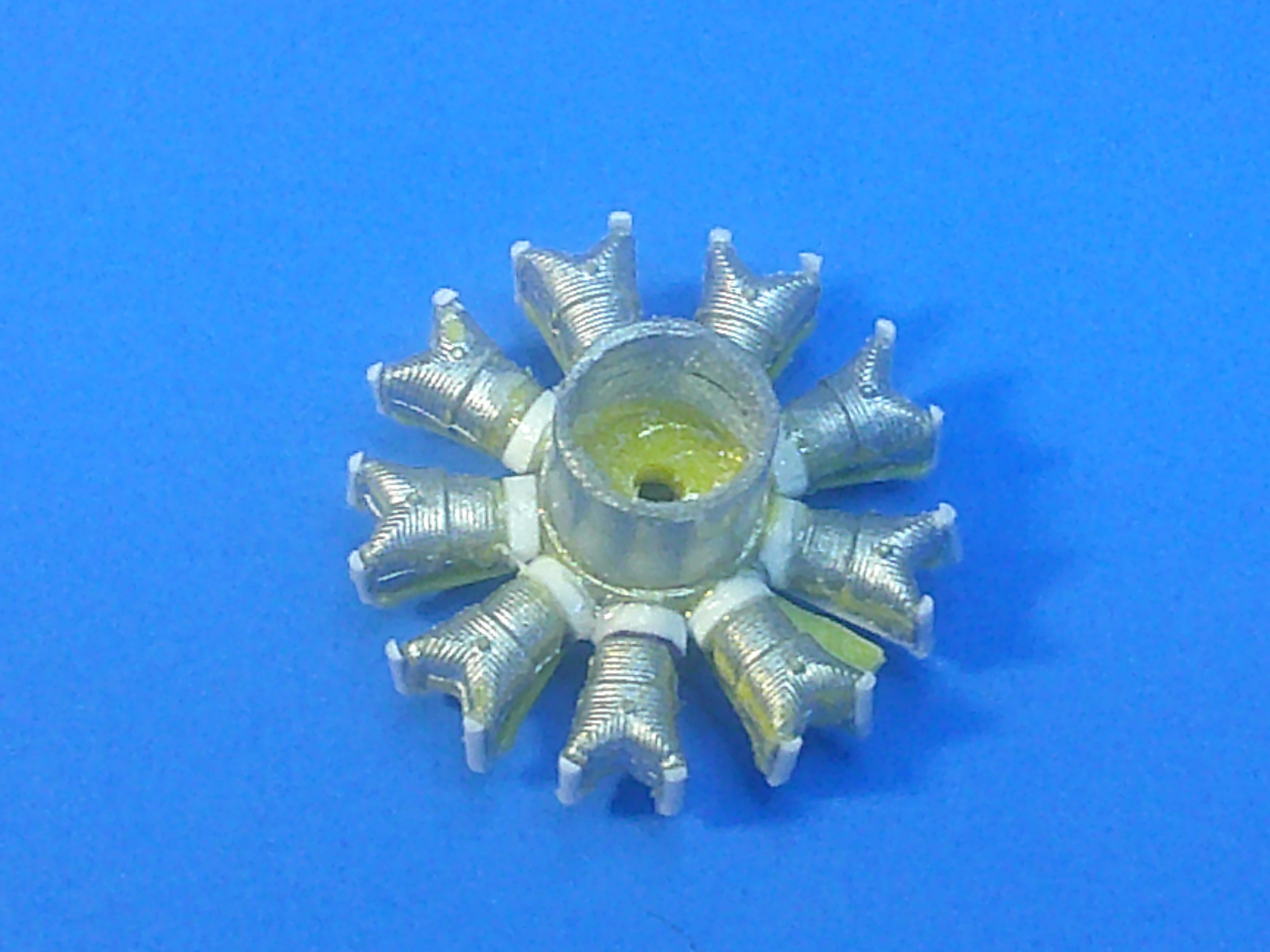
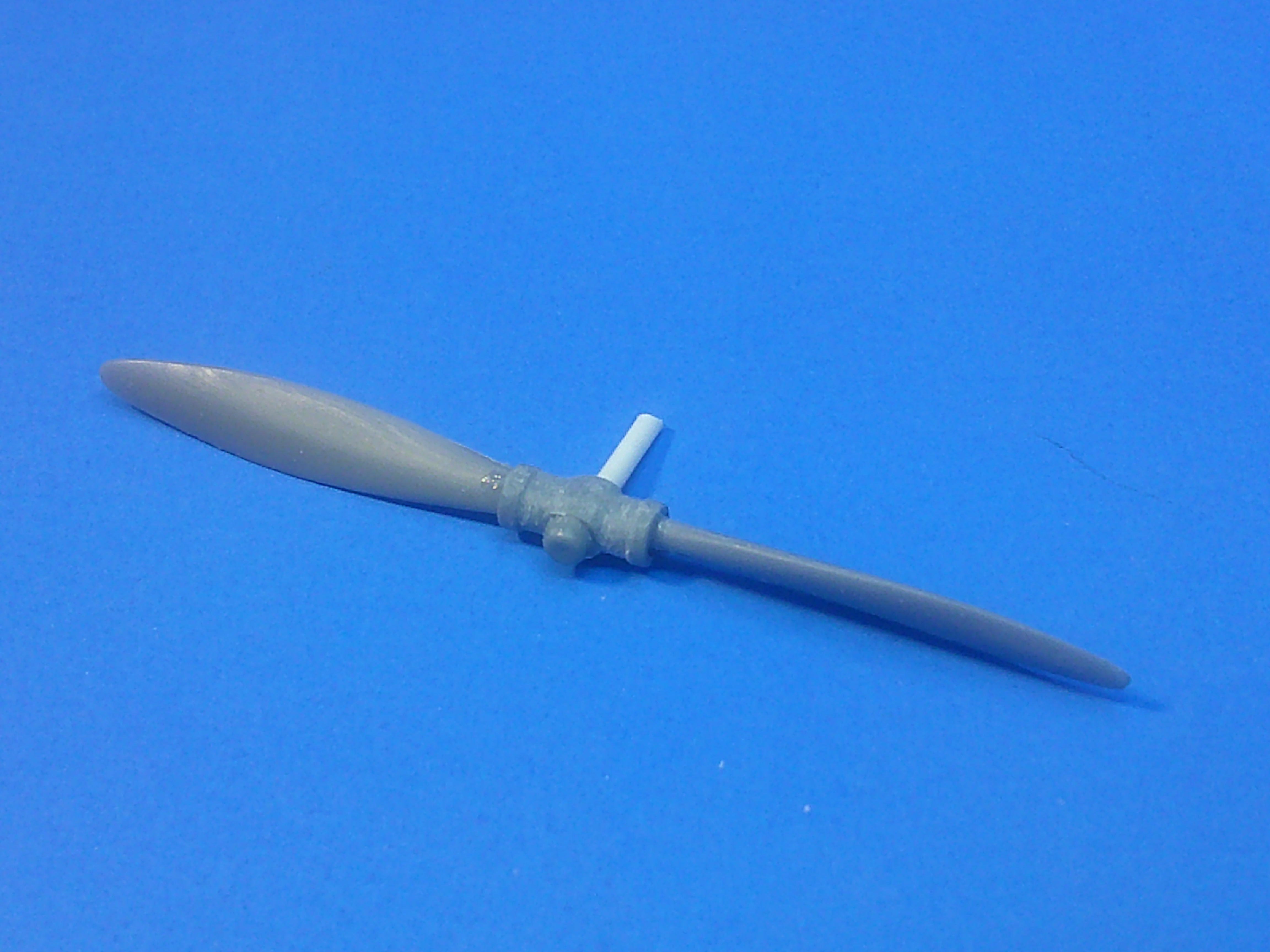
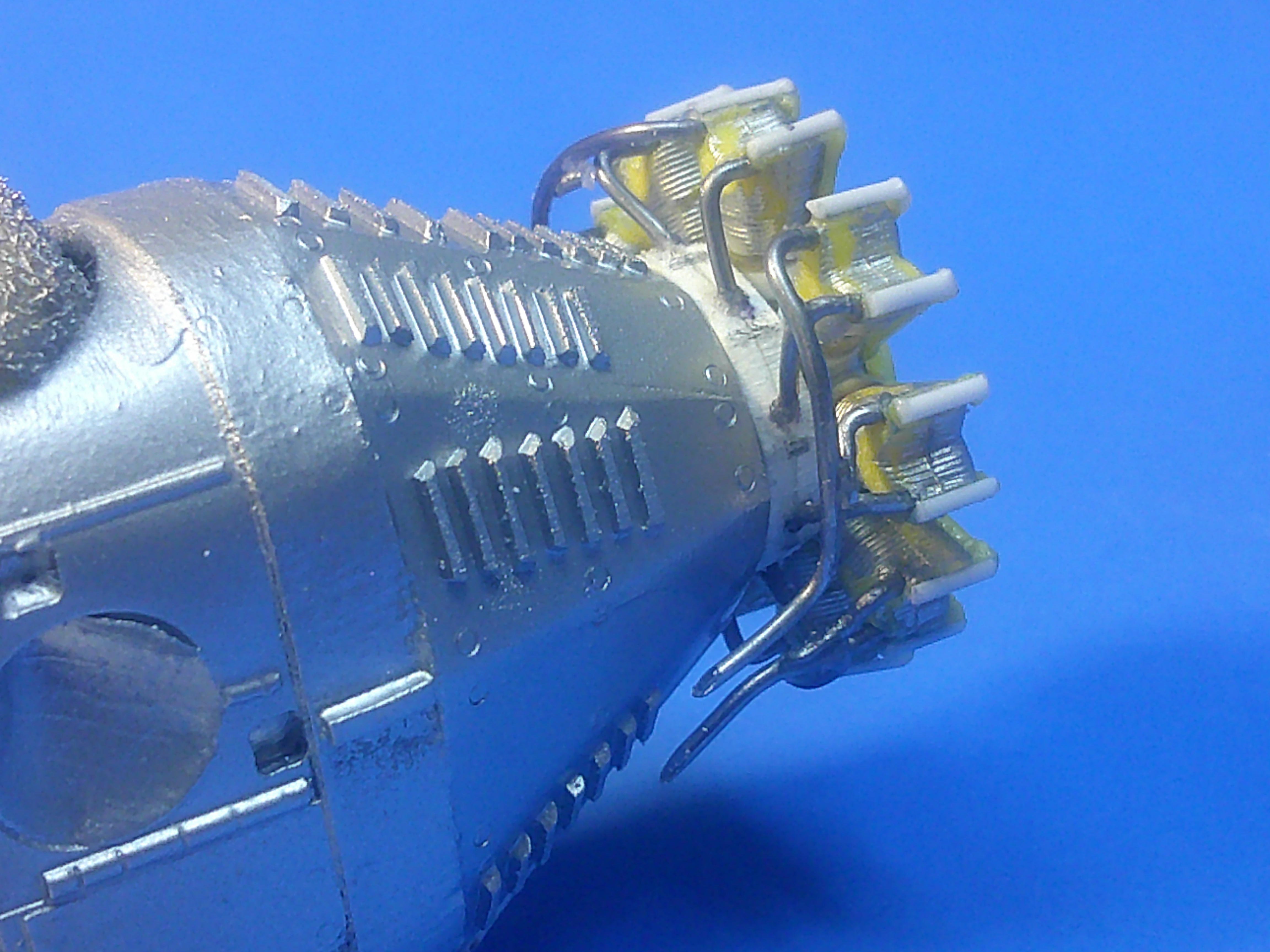
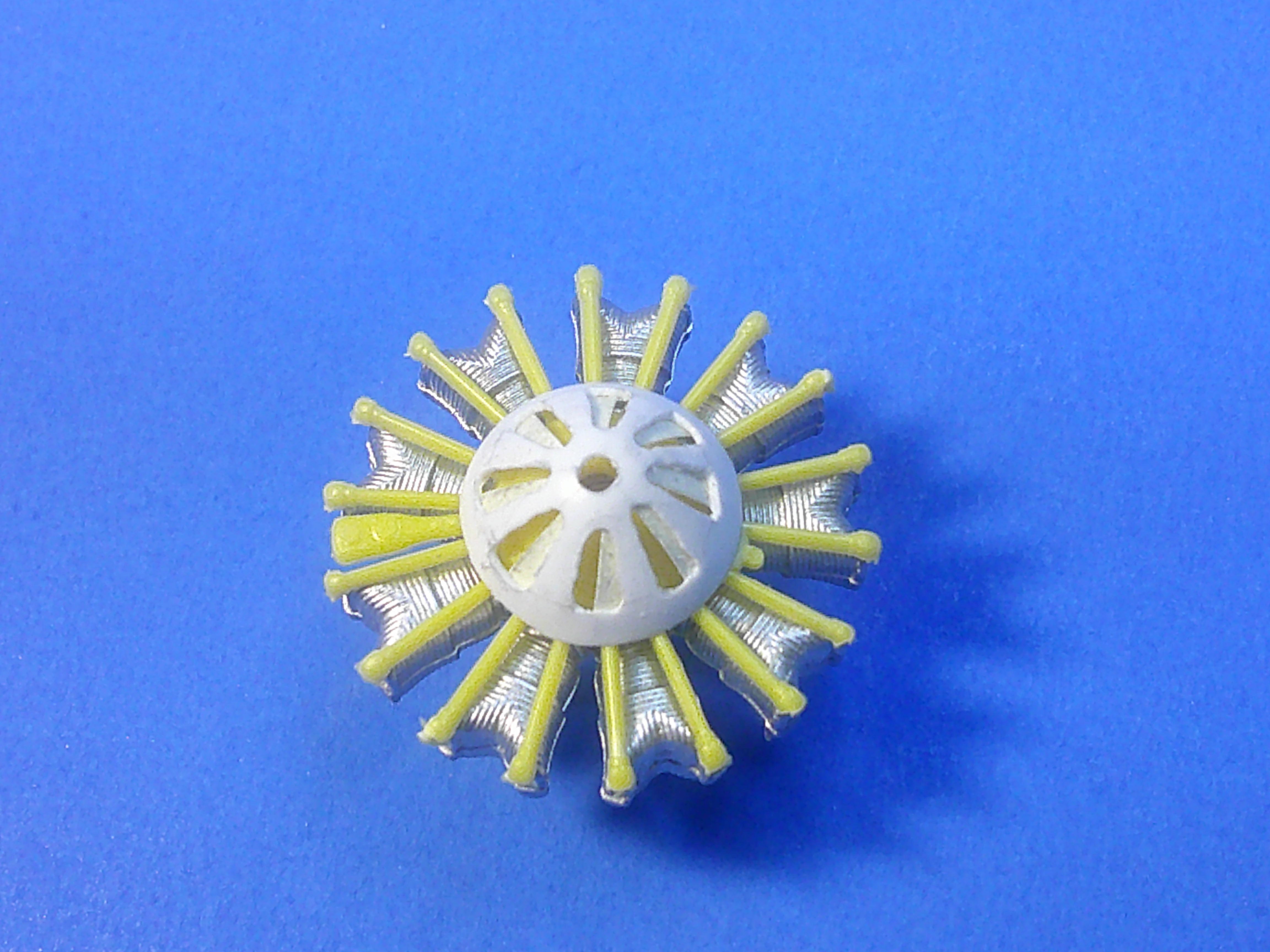
With the fuselage and wing in the filling/sanding/priming stages, I turned my attention to the engine and the prop..... For those of you old enough to remember when Saturday Night Live was funny, as Rosanna Rosannadanna said: "if it's notta one thing, it's a somethinga else"! Turns out the engine I had wanted to use (and every other engine on hand) was `1/4" too small in diameter. That's a scale foot too small! Since no one makes a resin P&W R-1690 that meant I'd have to "enlarge" the engine on hand. It was enlarged by first removing every cylinder from the crankcase and then installing thick punched discs at the bottom of each one. This pic shows the plastic sheet used to make the discs and the half round rod used to detail the tops of each cylinder. I used my trusty (and now rusty) old Waldron punch set to do the job! Since the cylinders were now longer, the original push rods had to be cut away from the crankcase cover and individually installed to fit. Since they'll all be covered by the oil cooler cover, those gaps at the bottom of each one won't be seen. Once the engine was the proper size and the front and cylinder tops detailed, I worked on the rear side.... The white intake/exhaust manifold ring was made by first drawing it on paper in order to get its 9-sided design and then copied onto sheet plastic laminated to the proper thickness. Holes were drilled in its top edges and into the rear or each cylinder for the intake and exhaust piping. Solder wire was then bent to shape and cut to length to make each set of pipes. Drops of superglue where pipes join will resemble "welds" after painting (I hope!). By the way.... as for the exhaust pipe arrangement.... I've seen at least 3 different "ways" in various pics and so felt free to make this design with 2 sets of pipes for each side of the plane since I couldn't pin down any "one" accurate design. The 4 pics above show how the finished engine and exhaust piping looks when mounted. I may add a few more small bolt heads here and there for additional detailing, but it's essentially done. I had no prop of the proper size either in my spares box and couldn't find one to order either so I "Frankensteined" one from spare prop hubs and blades. It still needs some cleanup here and there (the blades will be chromed!) and I may also add some counterweights for detail, but it's also essentially done. I have to say I was a little bummed out when I realized I'd have to modify the engine, but it went much smoother and faster than I thought it would in the end, all of the above work (including building the prop) taking about 4-5hrs. Now back to the fuselage! As always, critiques, comments, and questions are welcome! Gil
-
As you hear from them government types: I cannot confirm or deny that report either..... after checking several of my books...... I guess it may boil down to how much do you trust the researchers at Eduard? The last thing they'd want is to put decals in a kit that they could be gigged on by the modeling community. If you trust them, you can use them and always fall back on the "fault" lying with the manufacturer IF and when someone questions the insignia. The red surround star/bar was not in use for a long time, and generally added around existing stars, so the lack of white in the star portion of the insignia implies this was a totally fresh painting and not an addition to an existing insignia. BUT, the gray/white Atlantic scheme was also relatively new then too, so a repaint of the entire plane and then also of all of its insignia isn't all that odd sounding. Operations may have dictated the plane getting flown before painting the white in that last insignia was finished, but then it would've been nice for Eduard to specifically mention that to allay suspicions like yours. Unless someone here can provide a better answer, my only suggestion is to email Eduard and ask them what specific reference they based their kit markings on. Best of luck! Gil
- 5 replies
-
- 1
-

-
- eduard
- f4f wildcat
- (and 2 more)
-
I seldom use Testors Dullcoat anymore due to its tendency to yellow over time, but do have some on hand and can give this a try (the same method may work on other brands as well). Interestingly, this may help with the "yellowing" too..... I was probably spraying MORE Dullcoat on trying to get a "flatter" finish and all of that extra coating allowed for the yellow to show easier. Using this method may give me the flat finish desired with a minimal of clear coating and eliminate any yellowing down the road! Thanks for the tip! Gil
-
BIG STEP FORWARD..... the bottom wing and fuselage have been joined together! I've done the initial filling and sanding, but will wait to do the priming until after my model meeting today. The landing gear and wheels and empennage are all just sitting in position for the pics. I still have 4 major struts to add that attach to the fuselage and wings, but have finally reached the stage where they CAN be added. There's no turning back now! Gil
-
Piddly, but necessary work continues...... This pic shows the 3D printed Scarf rings bought for this project, the completed engine oil cooler cover (now with back plate). the scratchbuilt tail hook, and though hard to see the 3 windshields made and the tape pattern used to make them. Here's a test "sitting" of the windshields and Scarf ring. Note that 2 vertical posts have been added to the rear cockpit sides to support it. Test fitting the tail hook, which has a small wire post on the underside to serve as a locating pin. Still have a good amount of engine detailing to do too..... but I may just go ahead and get the fuselage glued to the bottom wing just so I can take something resembling an airplane to our model meeting Saturday! More pics then! Gil
-
Are you making all of the discs by cutting them from rod or punching them out from sheet plastic? Gil
-
Really nice blast from the past! Gil
-
Wow! Very nice and a rare subject too! Always good to see I'm not the only "vackaholic" on here.....Thanks for posting! Gil
-
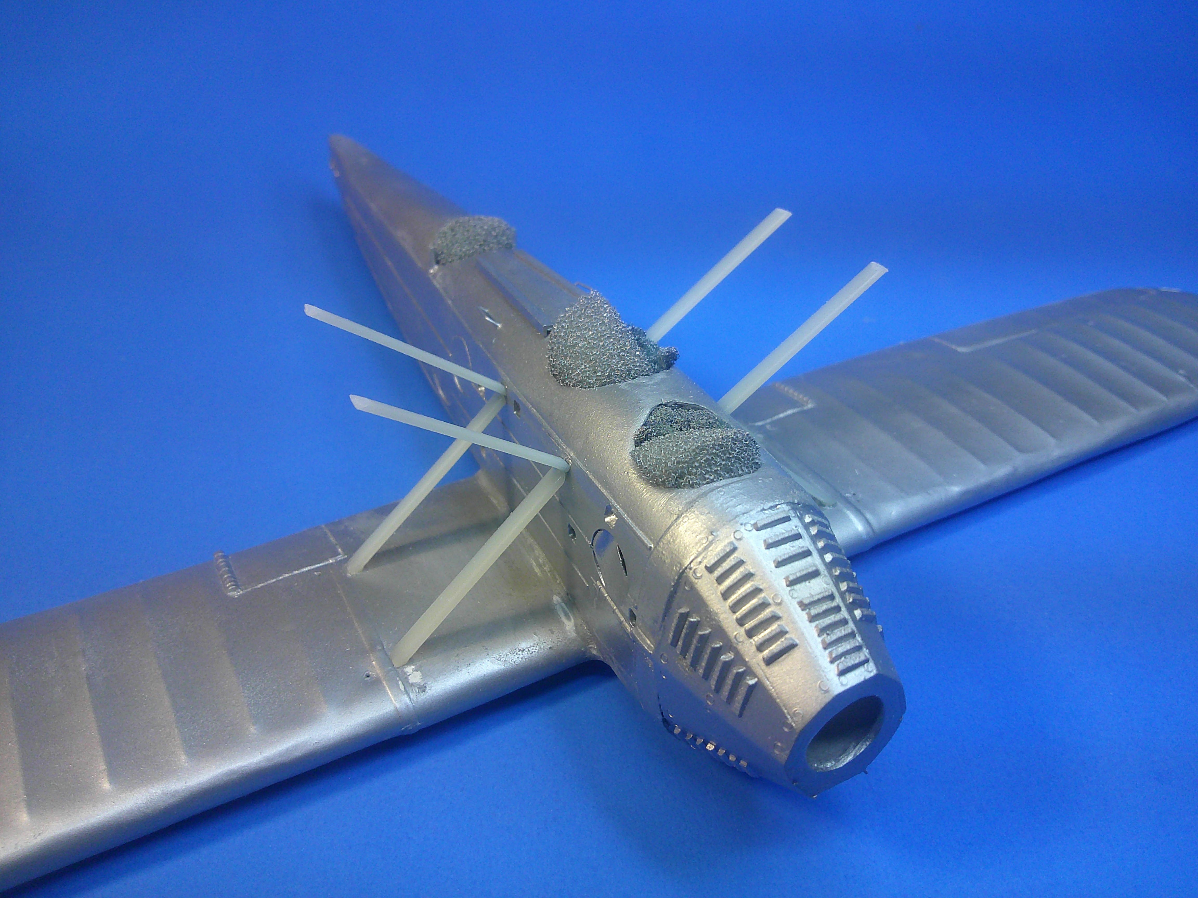
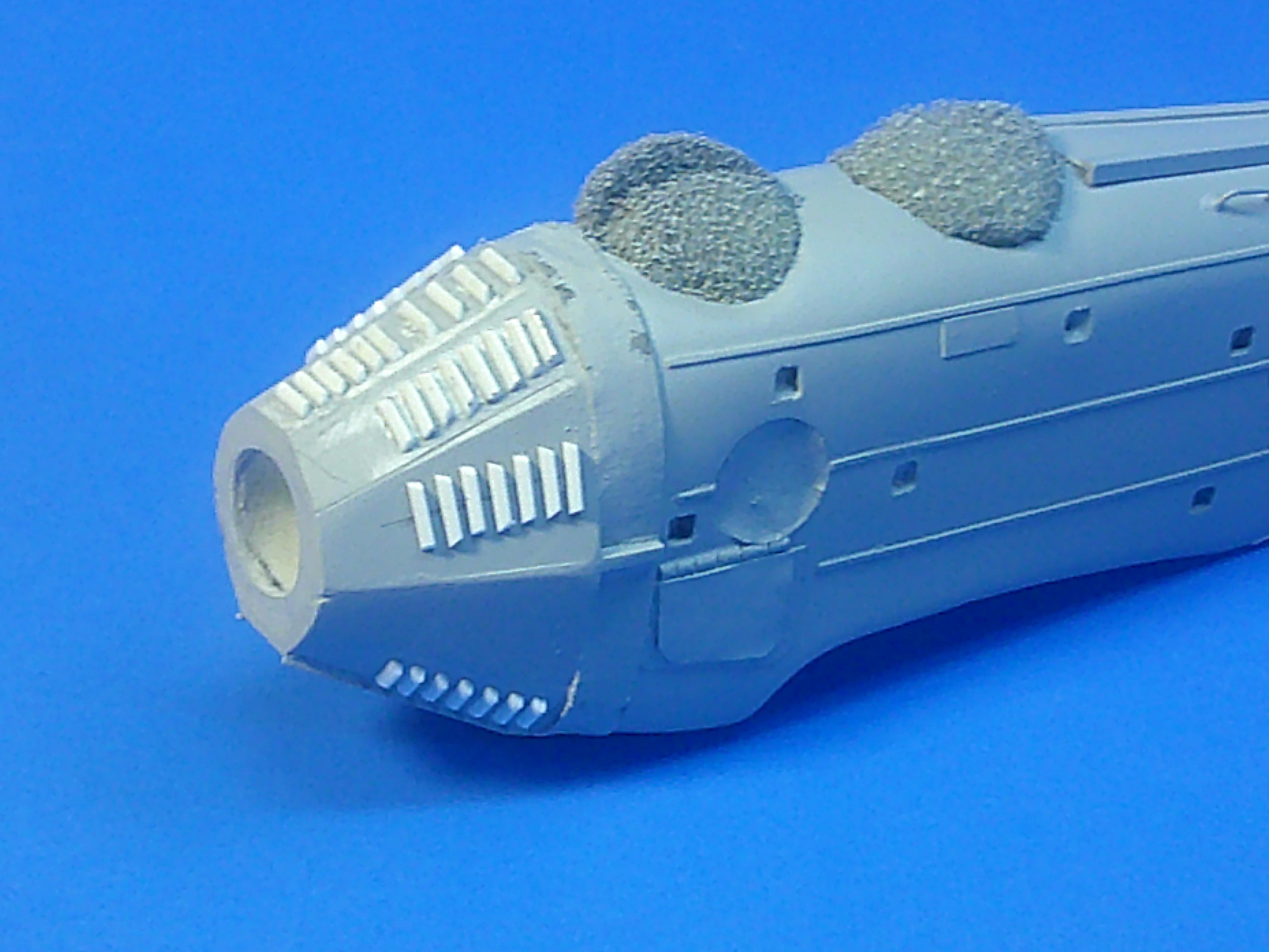
I got 2 more important steps completed today.... I added the vent louvers to the nose and also vacked and built up the engine crankcase cooling cover. I cut 1/4 round strip plastic pieces to as consistent a size as I could and then placed each one individually. There's more than 50 louvers on 7 of the nose panels. Note the the very top nose panel is the only one with a slightly different pattern to its louvers. I made the form for the cooler cover by sawing off the front of a 1/32 engine crankcase and then vacking over it on my Mattel machine.. The cooling slots were added by drilling and trimming each one. Here you can see how it fits to the engine, as well as the partially closed cooling slots. The slot doors were made by cutting thin triangular pieces of white plastic tape and pressing them into position on the inside. Each one was then superglued in place permanently. I've since also primered the louvers on the nose. Getting close to gluing the fuselage to the wings. More pics after it starts resembling an actual model airplane! Gil
-
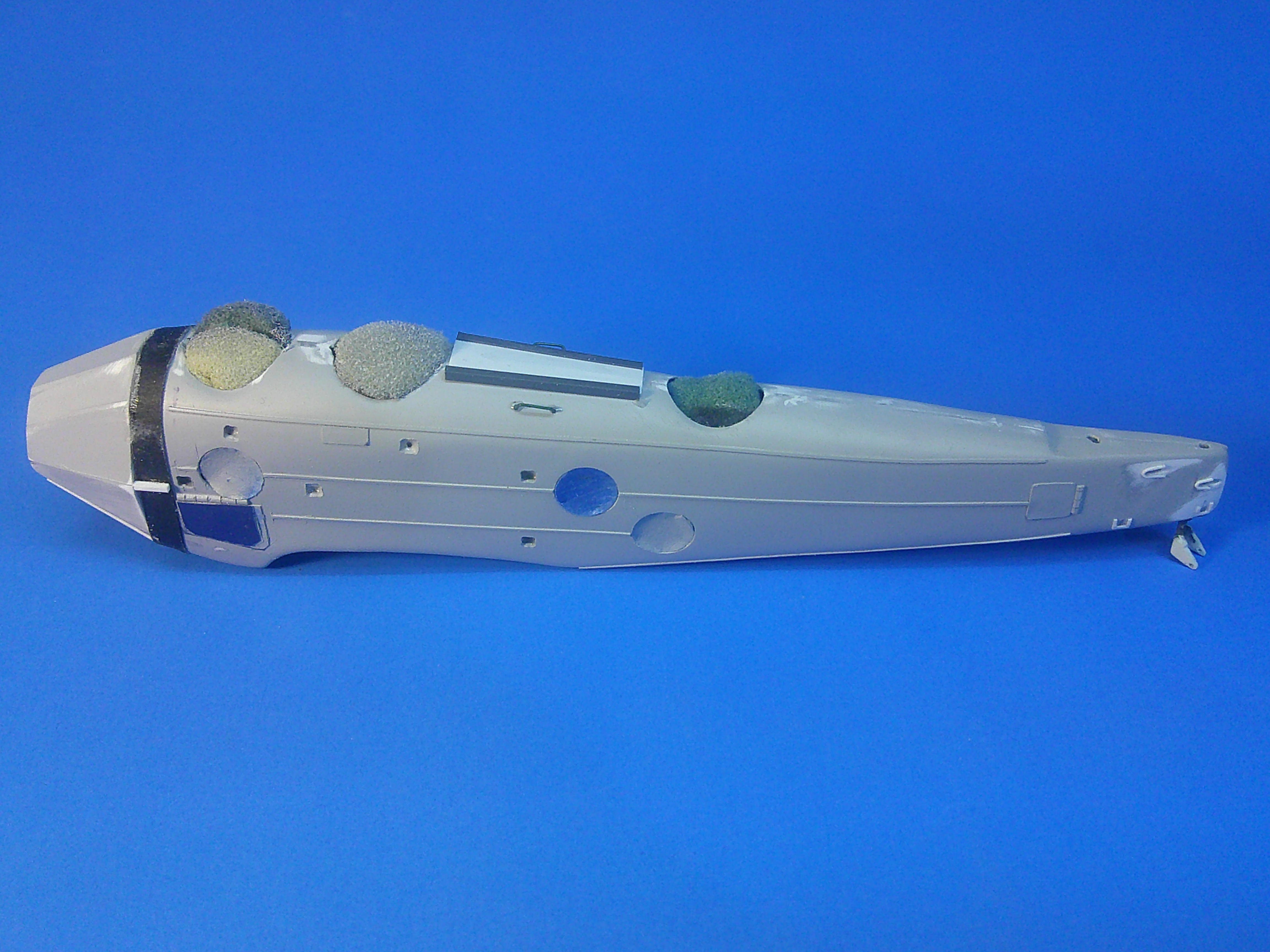
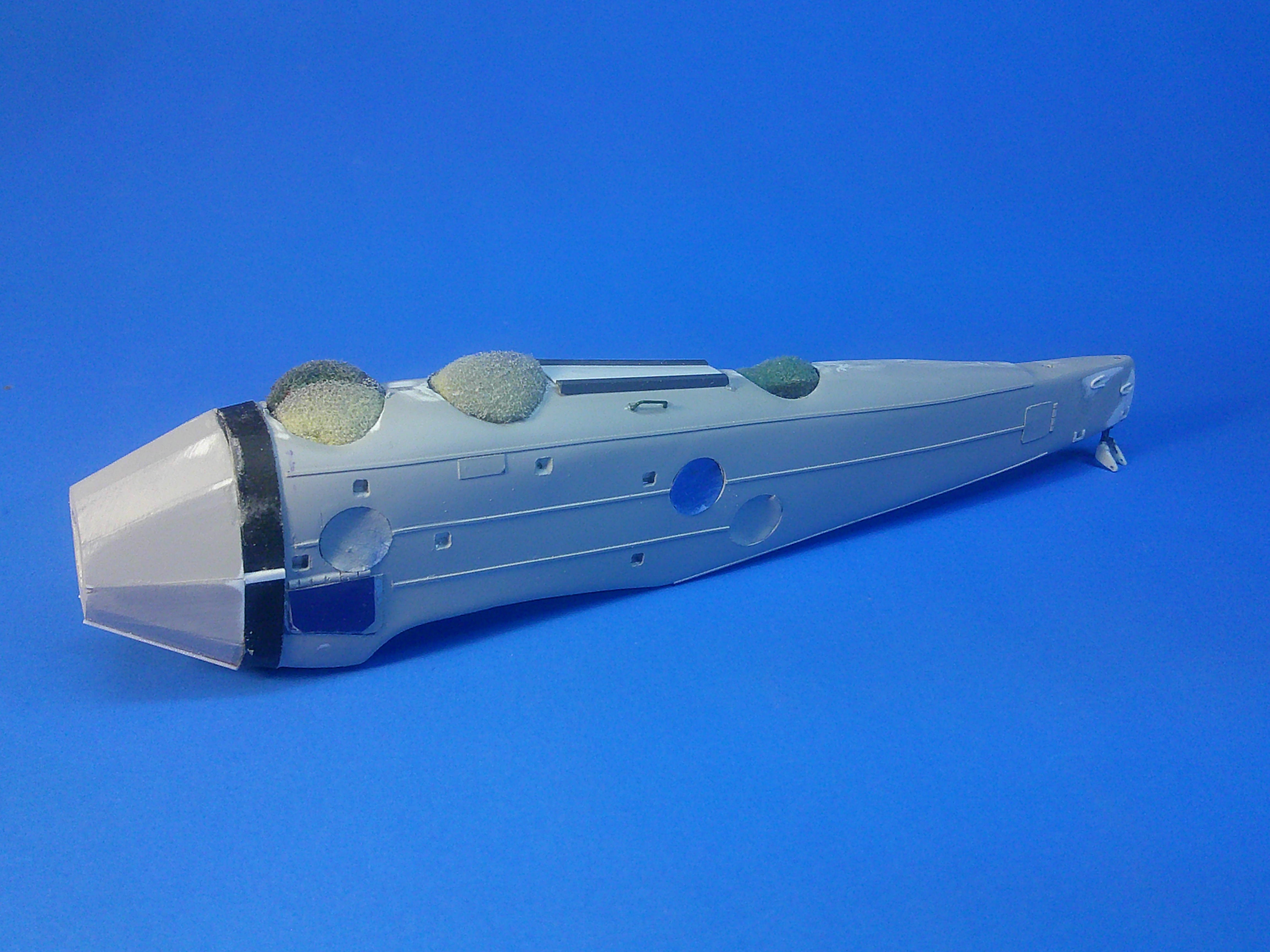
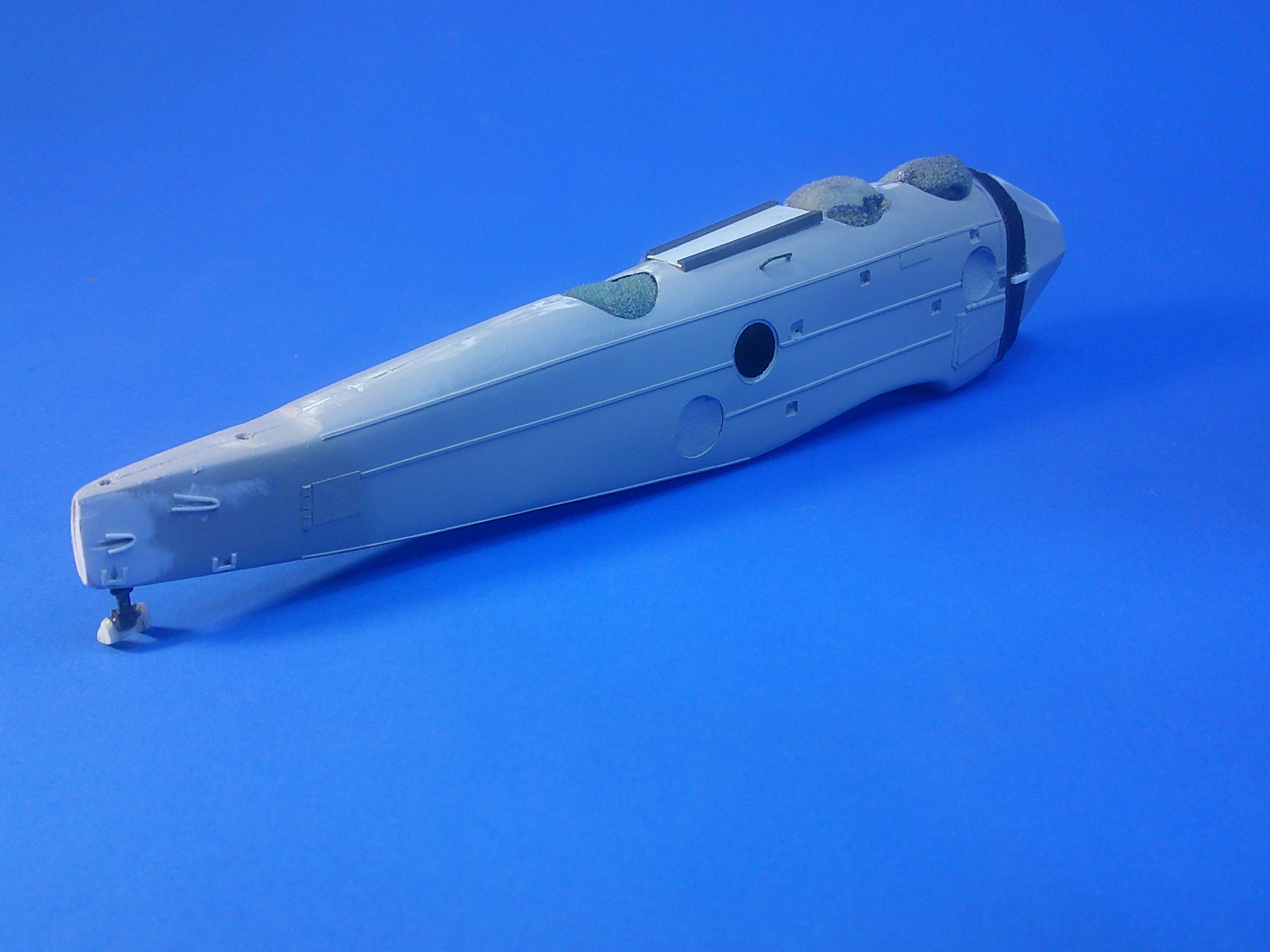
The fuselage is now mostly complete since the nose has finally been added! The main thing that jumps out in the pic is the bracing strip in front of the first cockpit. I used multiple layers of tape wrapped around the nose to do it. You can also see one of the masks for one of the window openings has come off during handling. Note the crawl platform that's been added between the pilot and gunner's cockpit. It's just a plastic sheet bordered by upside down "L" shaped strip. In addition to the nose reinforcing strip, note that I repaired the forward access panel and also added a wire grab handle near the crawl pad. This view shows the scratchbuilt tail wheel and a closer look at the rear sides shows the reinforcing strips added around the areas for the control wire holes and the tail plane underside brace points. Next up is another round of filling and sanding imperfections, but it feels good to seemingly be making faster progress! Comments, questions, and critiques welcome, as always! Gil
-
3 very mundane pics...... But they show a very MAJOR step forward in that the fuselage halves are together and the first coat of primer applied! It even sort of resembles an aircraft fuselage! The next steps are to finish applying most of the features that still need to be added to the fuselage, or at least get their areas ready. These are things like the the platform between the pilot and gunner's cockpits, tail plane brace brackets, elevator and rudder control wire holes, the reinforcing strip around the nose, making the windshields, tail wheel socket, etc. It doesn't look like much, but you can see how much work was needed JUST to make this step possible if you glance back to the beginning. Hopefully I'll make progress at a little better rate from here to the end. Gil
-
Excellent display of scratchbuilding! Gil
-
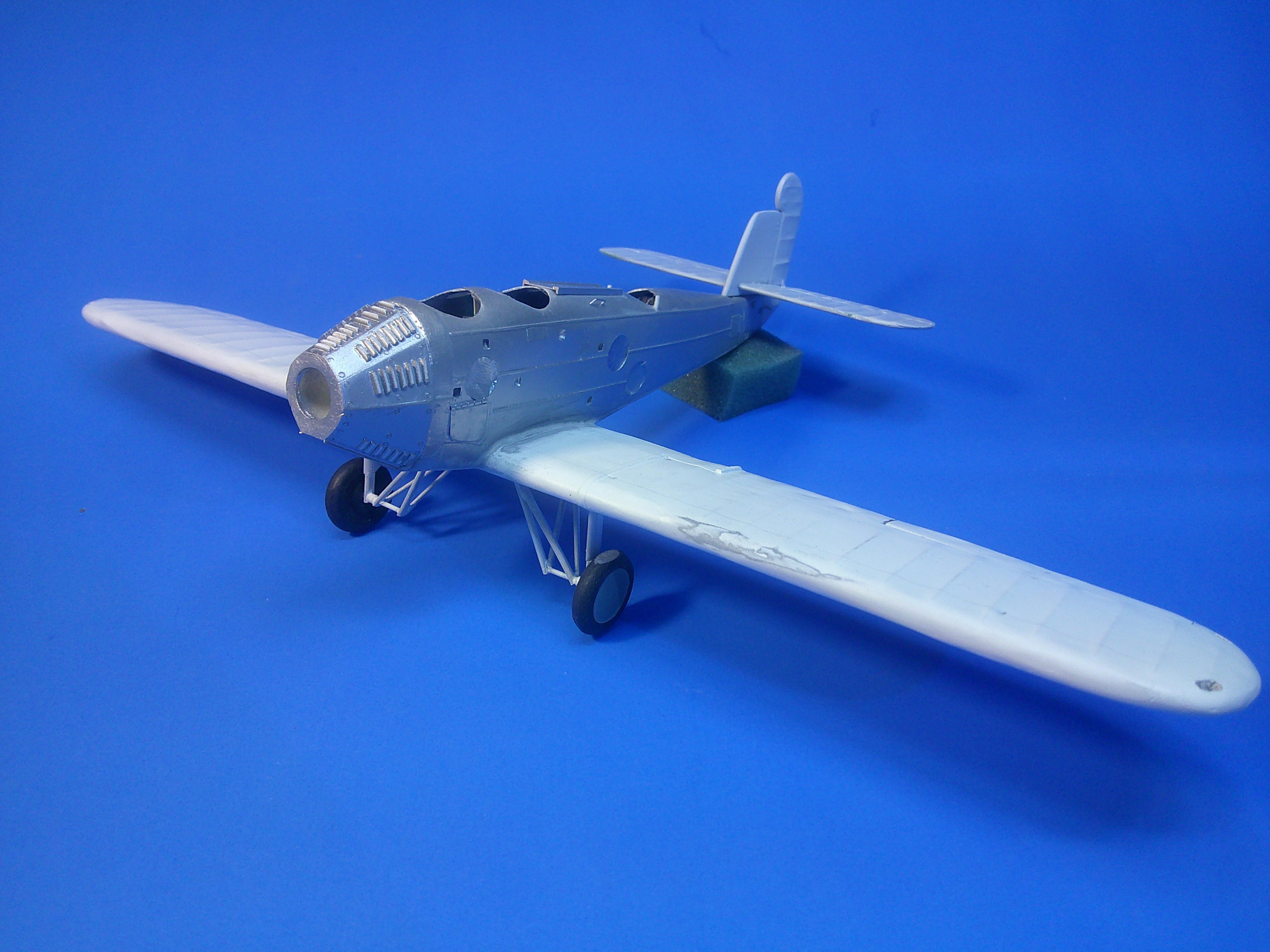
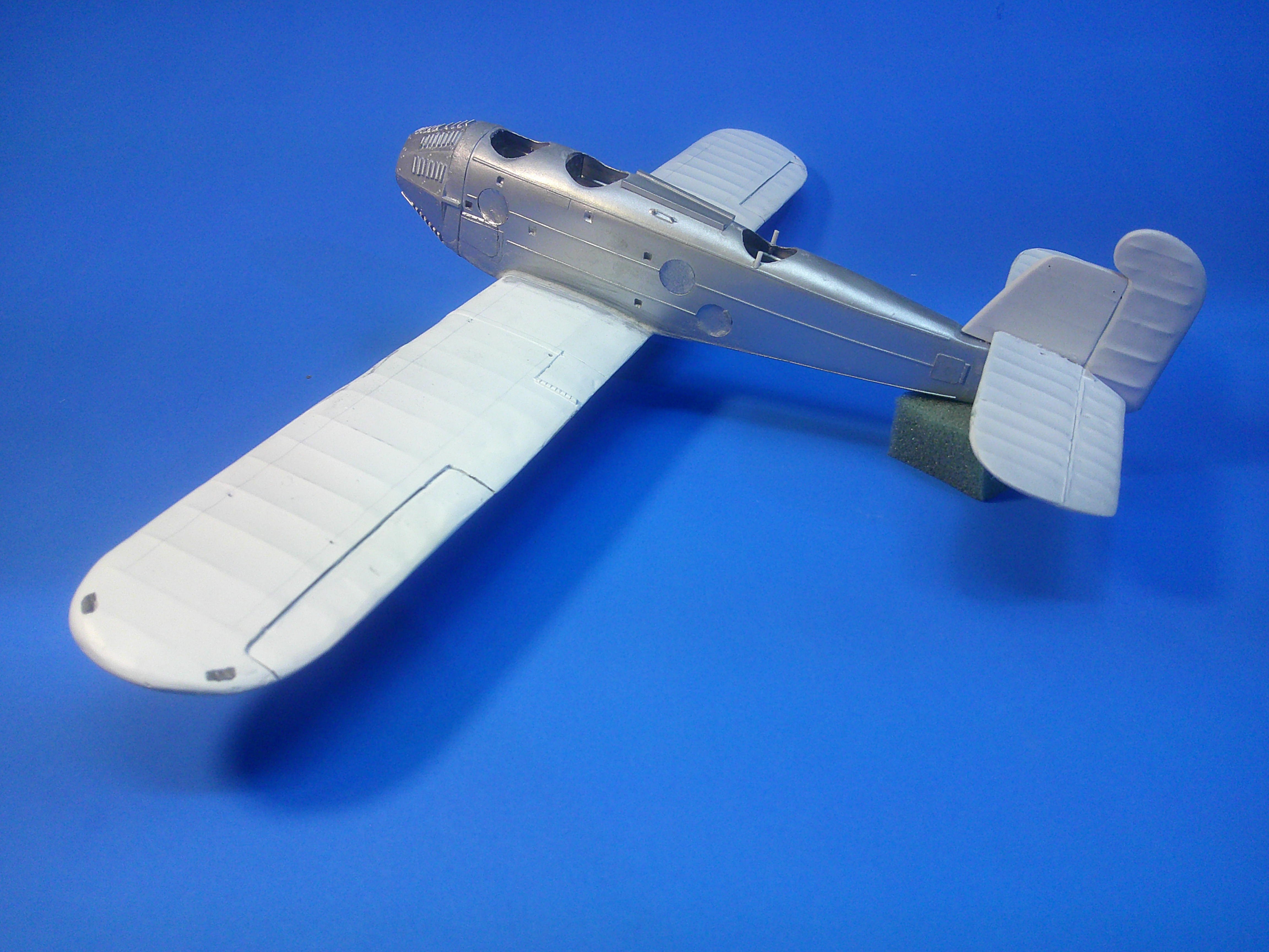
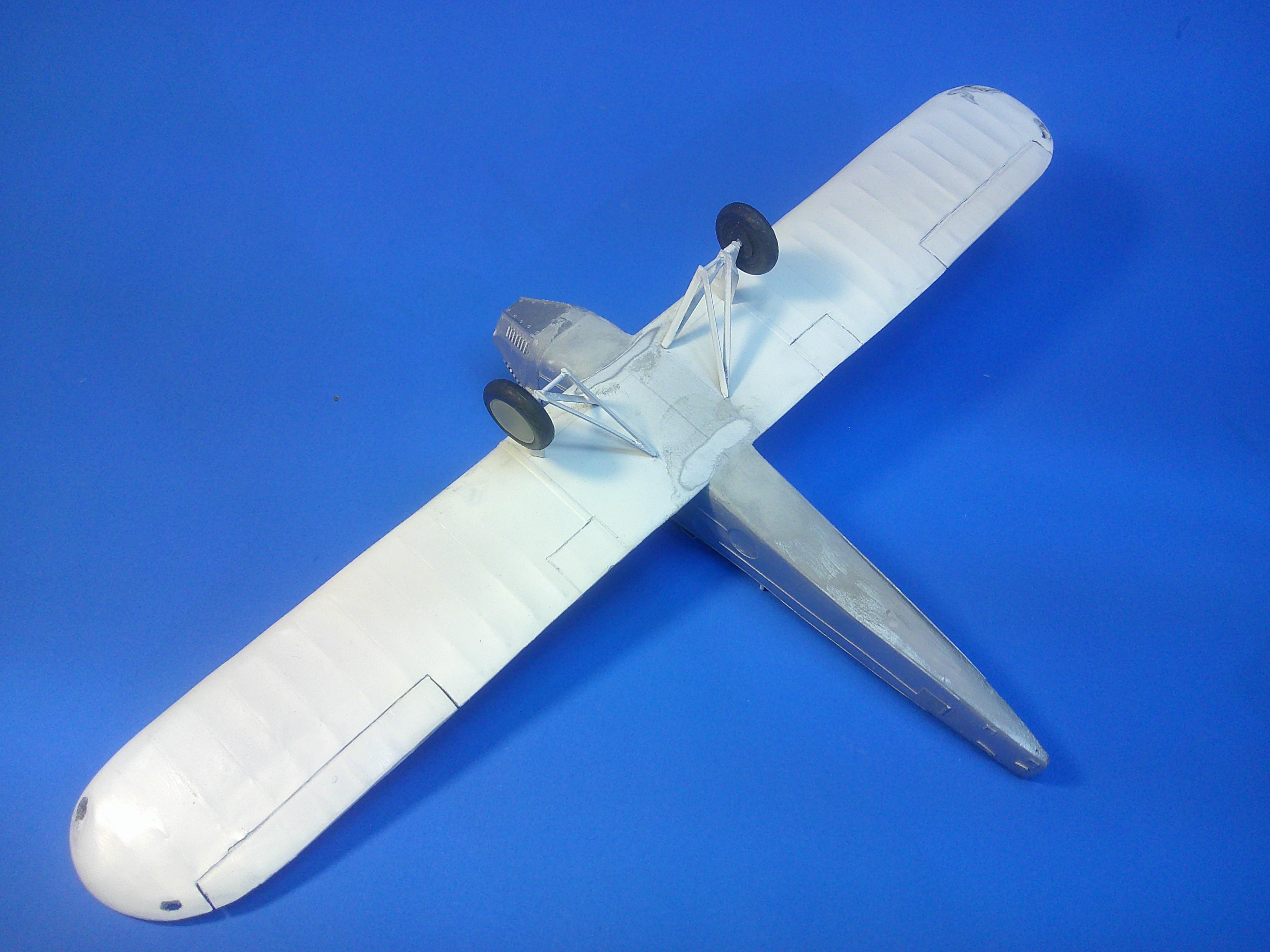
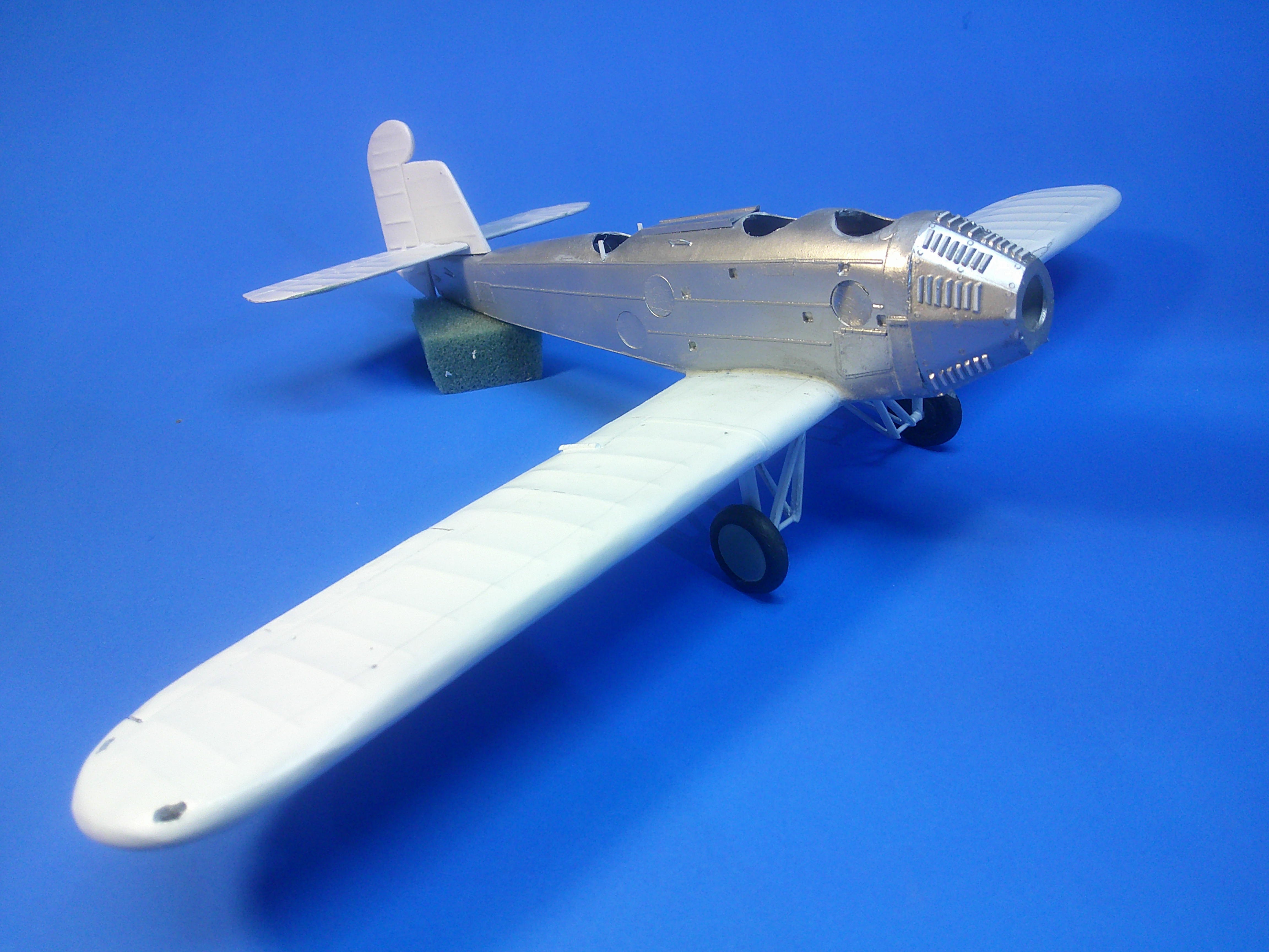
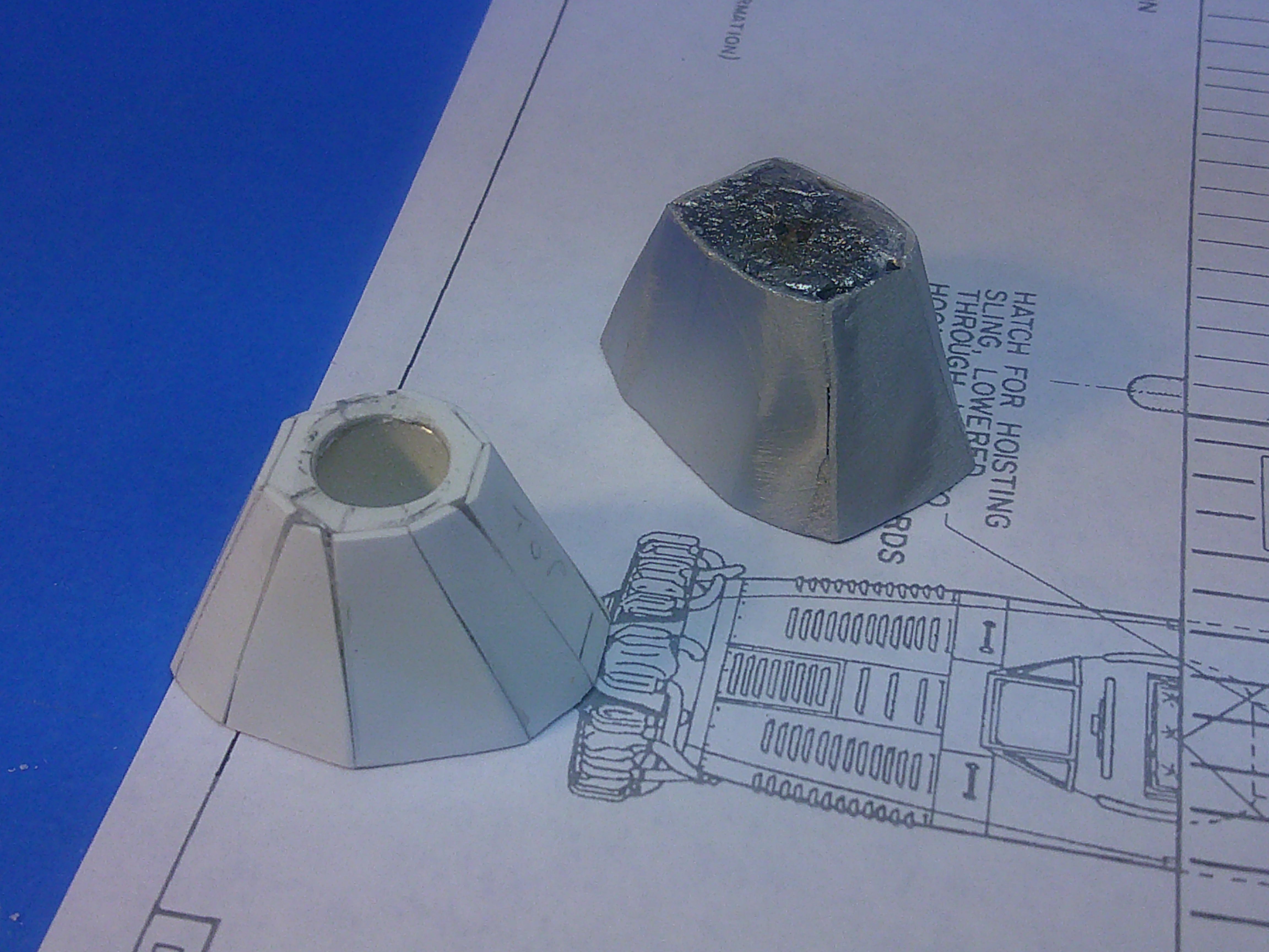
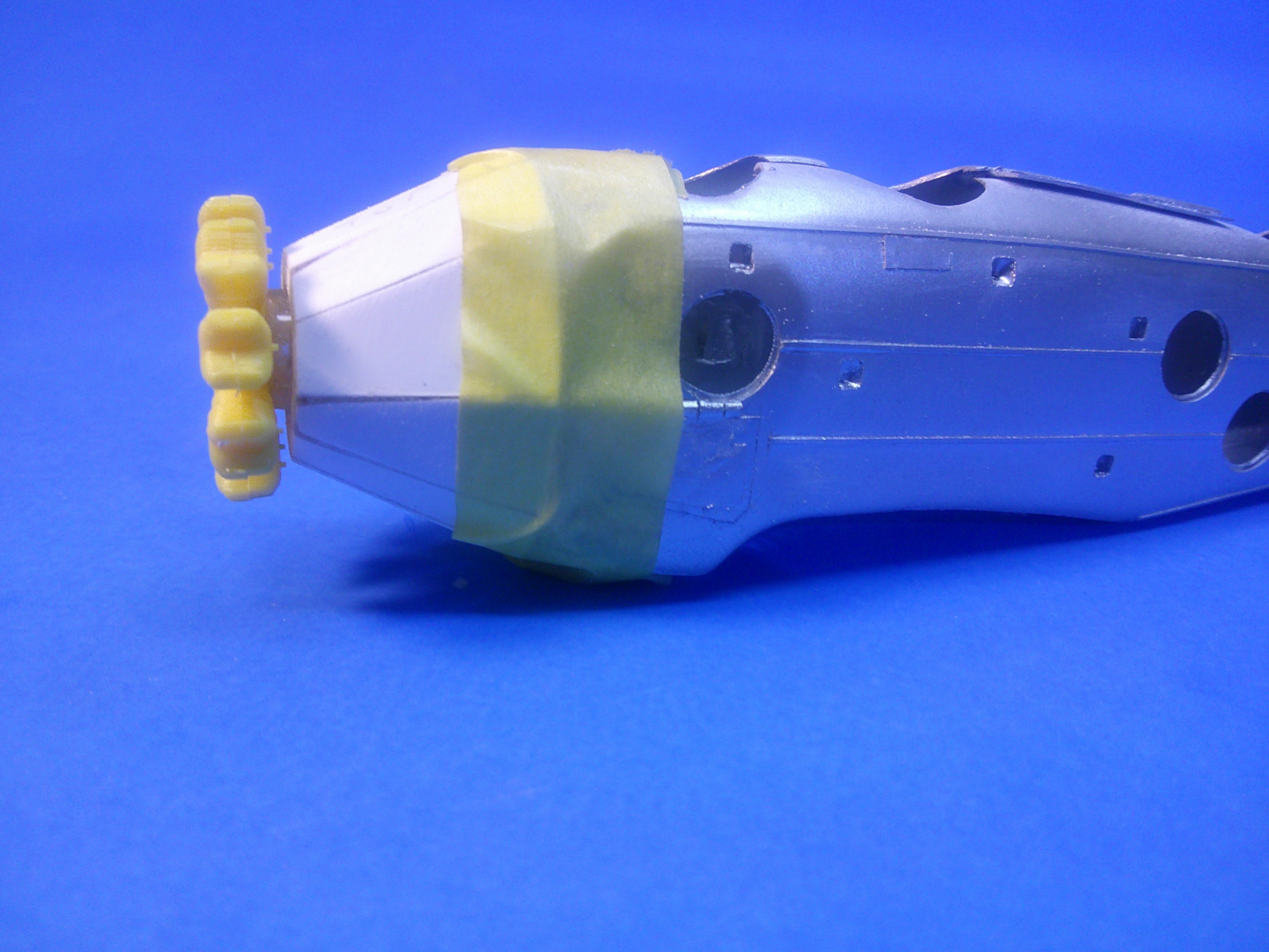
Part of scratchbuilding is having to rework and rebuild things along the way. I wasn't satisfied with the original nose I built for the 1/48 T4M-1; so I started over from "scratch" and built what I think is a better one. The back plate matches the front of the vac fuselage, The front octagonal plate establishes the end of each section as well as gives the front measurement for each. Note the engine with tubing glued to its back that will fit into the nose when done. Shot of test fitting the engine.... there's some room to move the engine in or out to allow for the exhaust manifolding on the back to be built up later. As you can see, the original nose had a top panel that was much too wide and each of the other panels weren't as well defined. By building the new nose using flat panels cut to shape I could get the top center panel the correct size and make each one's "match" on the other side of the nose the same size until it was filled in all the way around. Note all of the air louvers on the drawing that will need to be added before I can call the nose "finished". Test fitting the nose to the fuselage. Although it is slightly larger in diameter where they meet, there's a thin "proud" strip that wraps around the nose just in front of the front cockpit that will help even out that difference. It can't be added until after the fuselage has been glued together. With some luck this will be the last major "build" job of this project and I can get the vacuform fuselage halves glued together and the nose added to complete the fuselage. Hopefully, after that, the rest will be simply a matter of normal parts detailing, gluing and aligning, and other such "mundane" work as done to complete any other model. We'll see! Gil
-
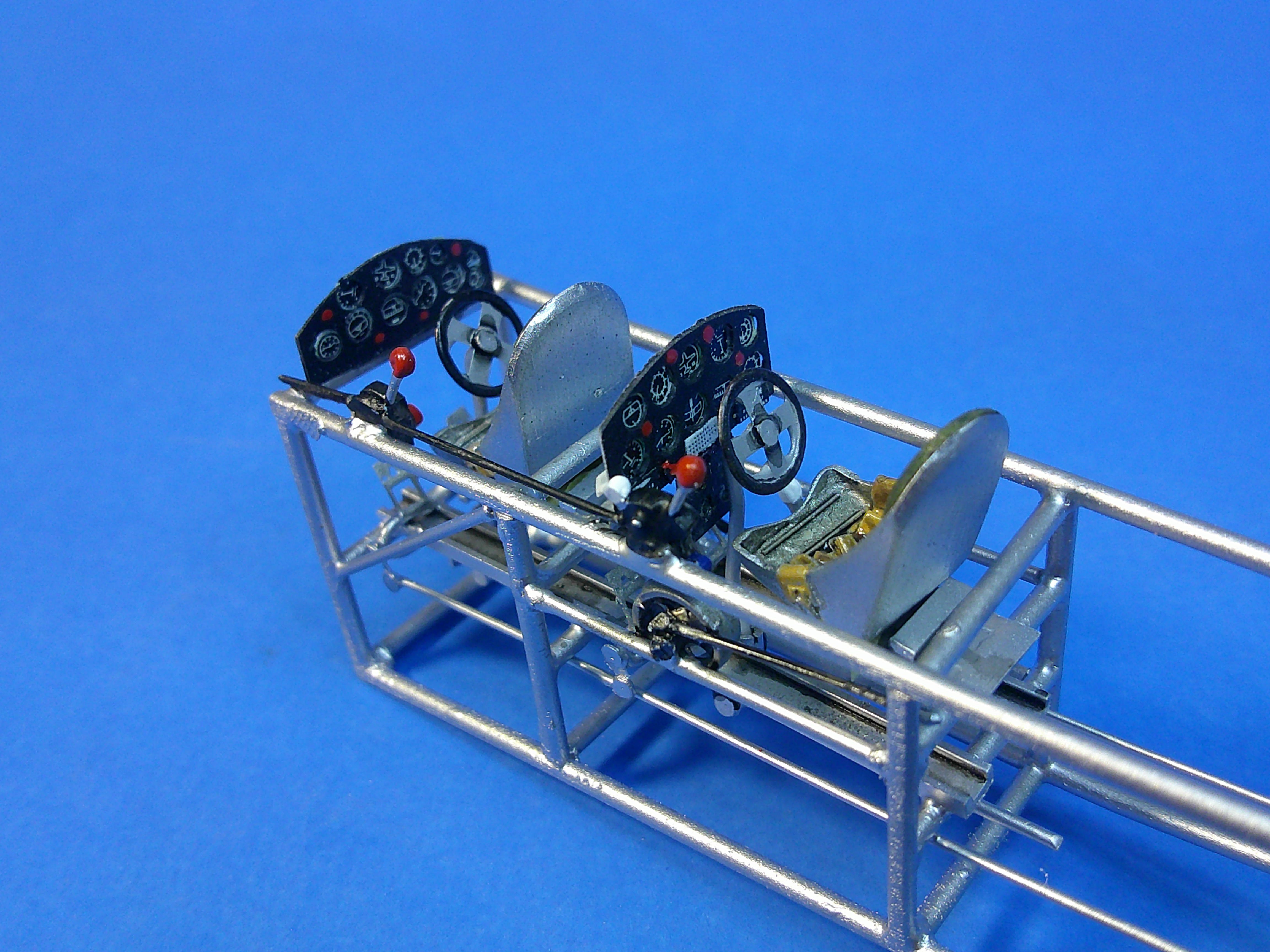
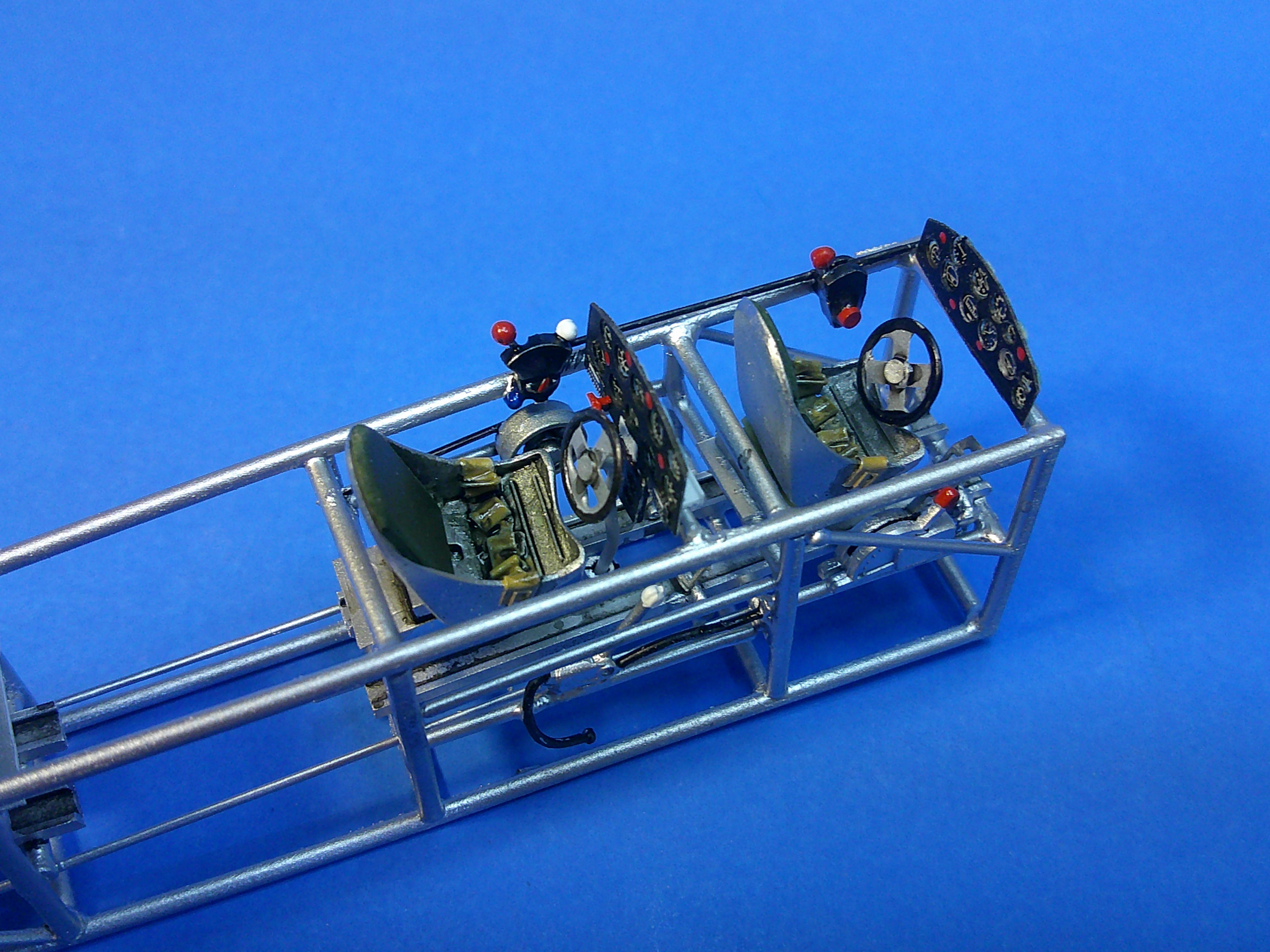
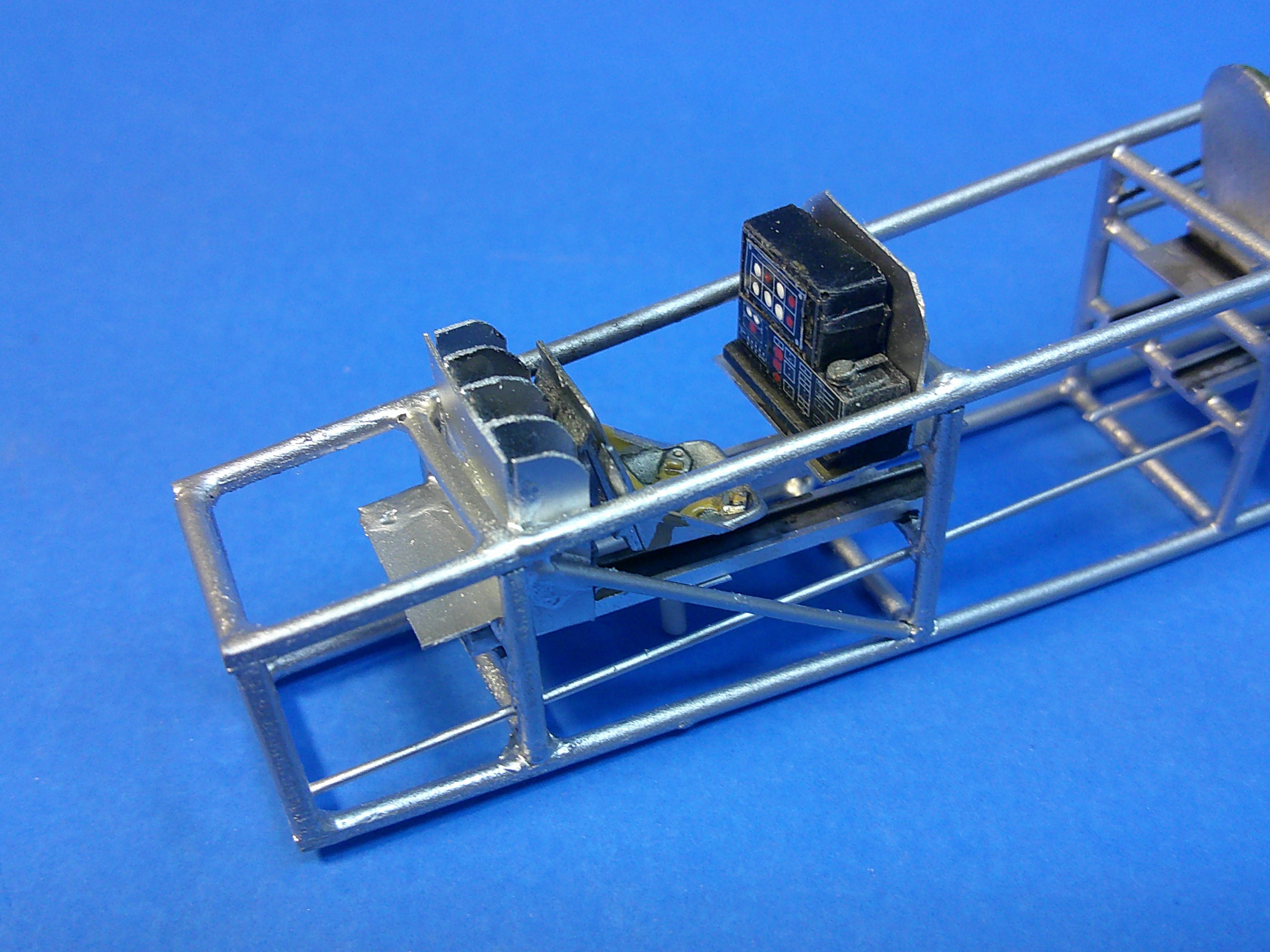
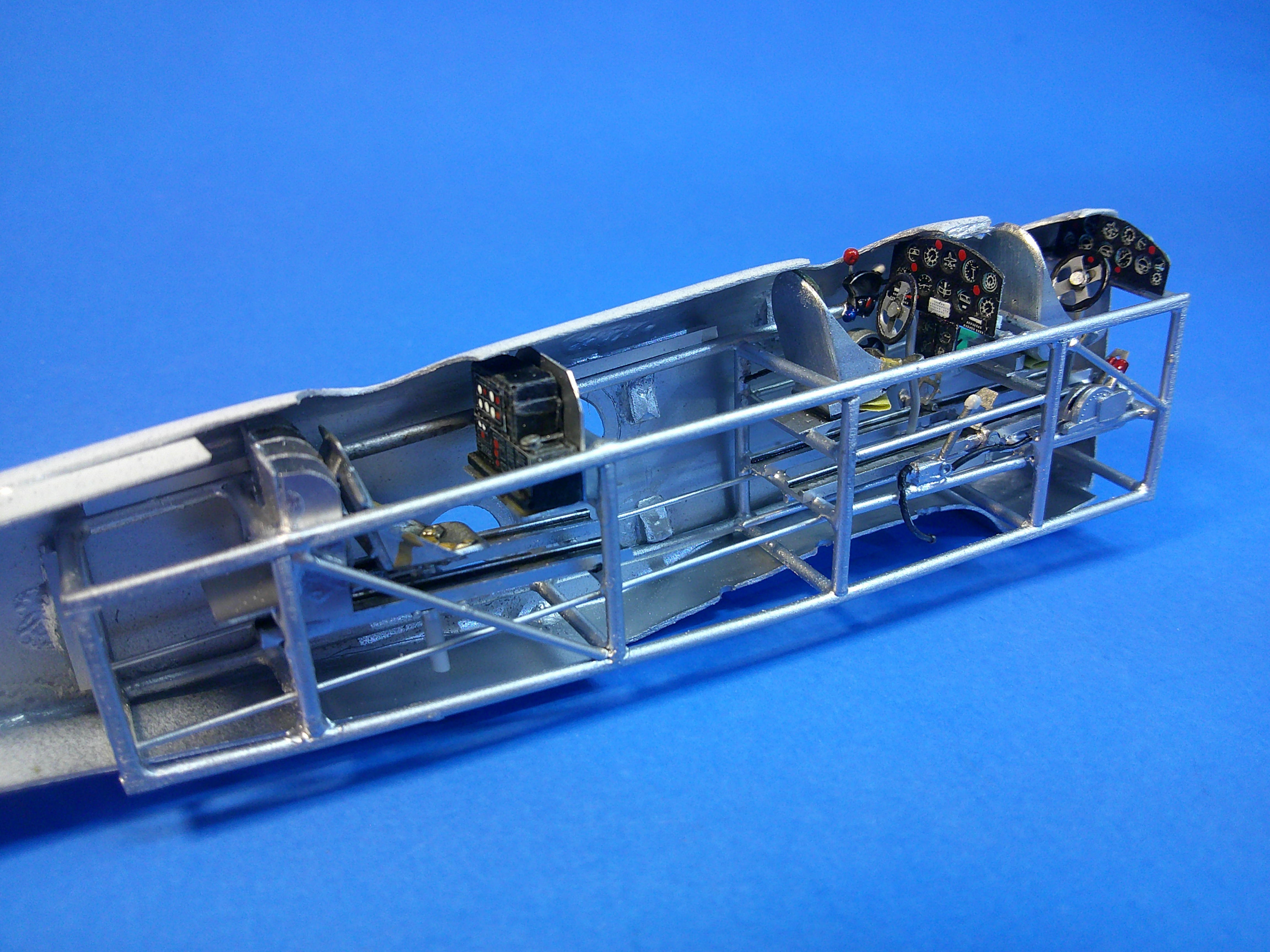
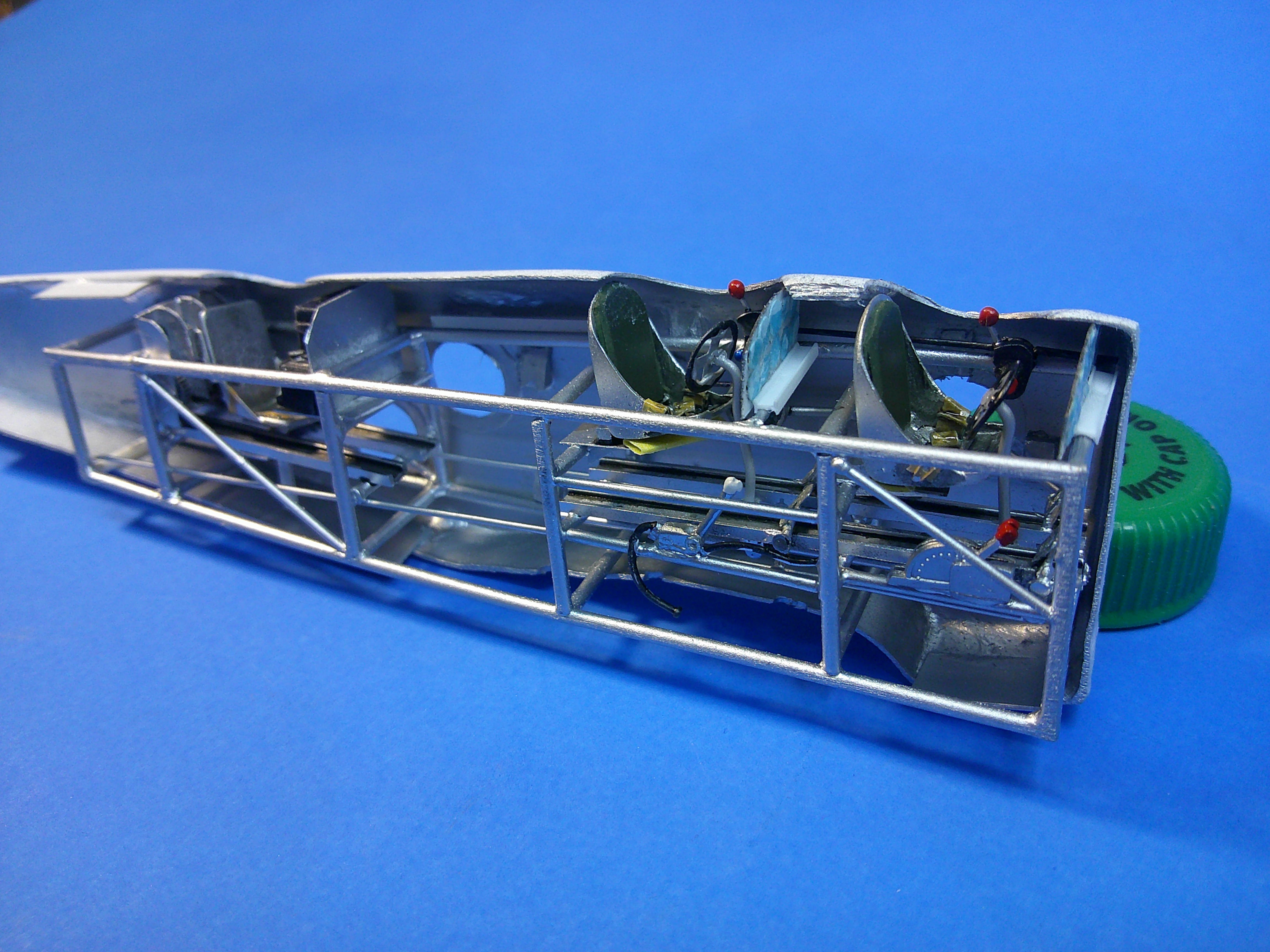
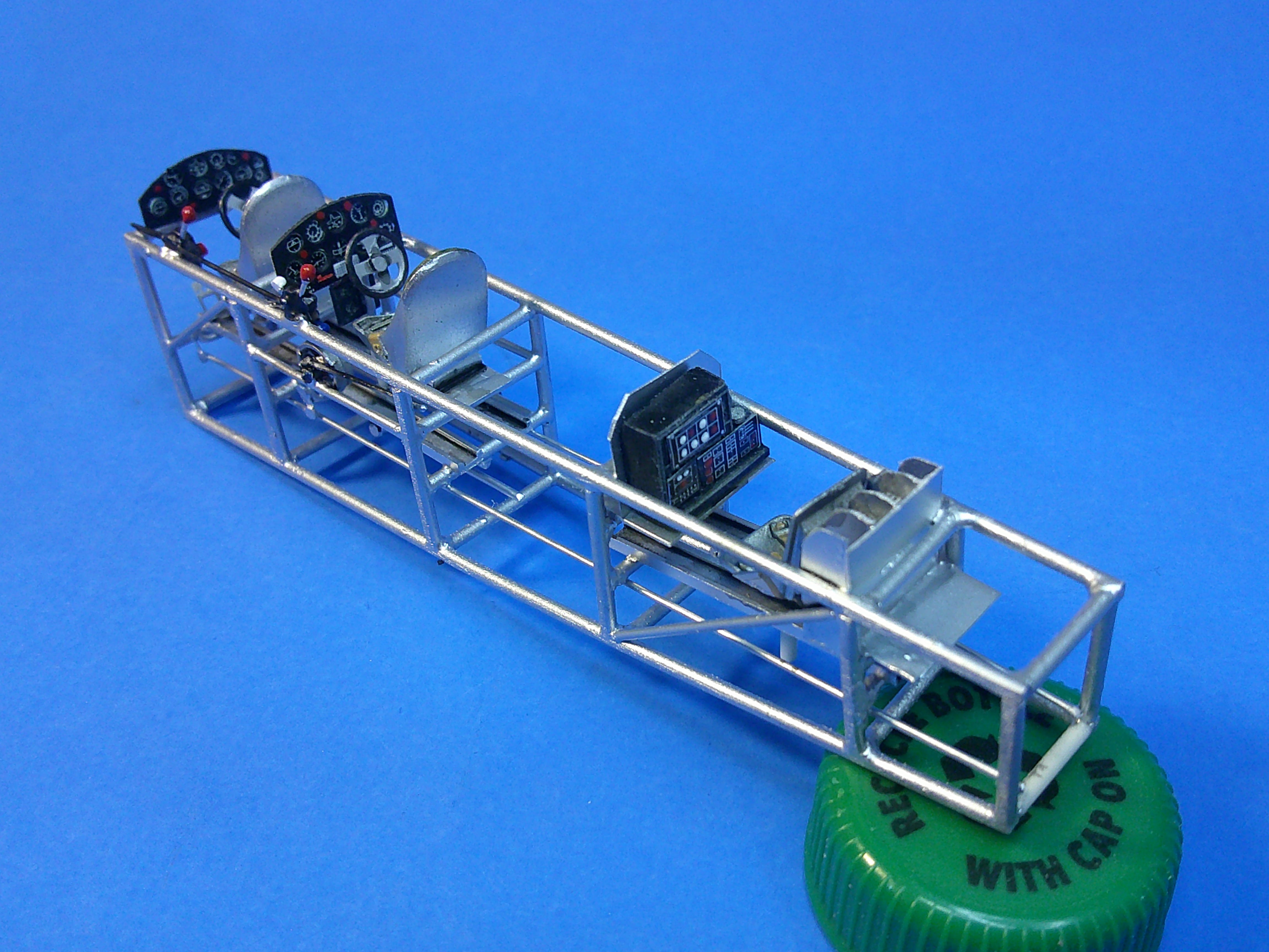
I'm calling the interior work "done"..... These 2 pics focus on the front 2 cockpits from both sides. The Instrument panels are glued in place, but the seats and the control wheels are not. These 2 pics give a view of the rear cockpit with the radio, its sending key on the side, the swivel seat, and the Lewis drum storage racks. What really can't be seen are the 6 3D printed Lewis drums in the racks. Like up front, the rear seat is not glued in yet. These 2 pics show how it all fits relative to the cockpit openings and the side windows. For the "record"....none of this is "accurate", but most of it is what I term as "period authentic"; meaning it's typical of most all of the important items that would be found and/or seen in biplane cockpits from the late '20s and early '30s. There isn't a single Martin T4M torpedo plane left in the world to serve as a reference, only a couple of poor pics of its cockpits and IPs, and most other pics are from longer distances where details are hard to discern. The drawings available do help, but even they have limited "views" and are of no help for the interior. So I'm settling for some generic cockpits that at least look somewhat "busy" for anyone who wants to peek inside! Now on to that pesky octagonal nose section that still needs to be added! Gil
-
Excellent tutorial on using simple materials that are layered to build up something to authenticity! Gil