Leaderboard


Popular Content
Showing content with the highest reputation since 08/04/2026 in all areas
-
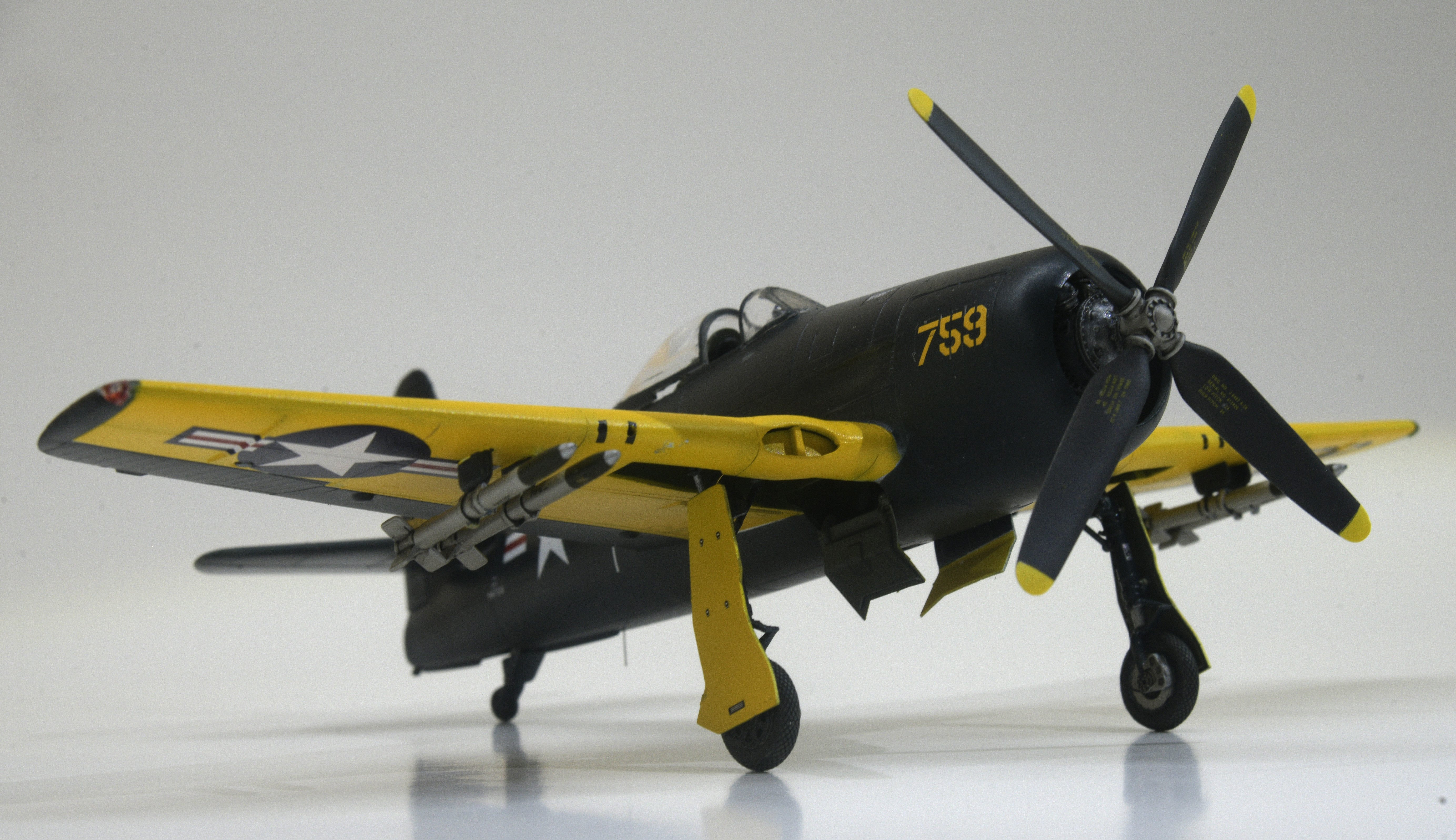
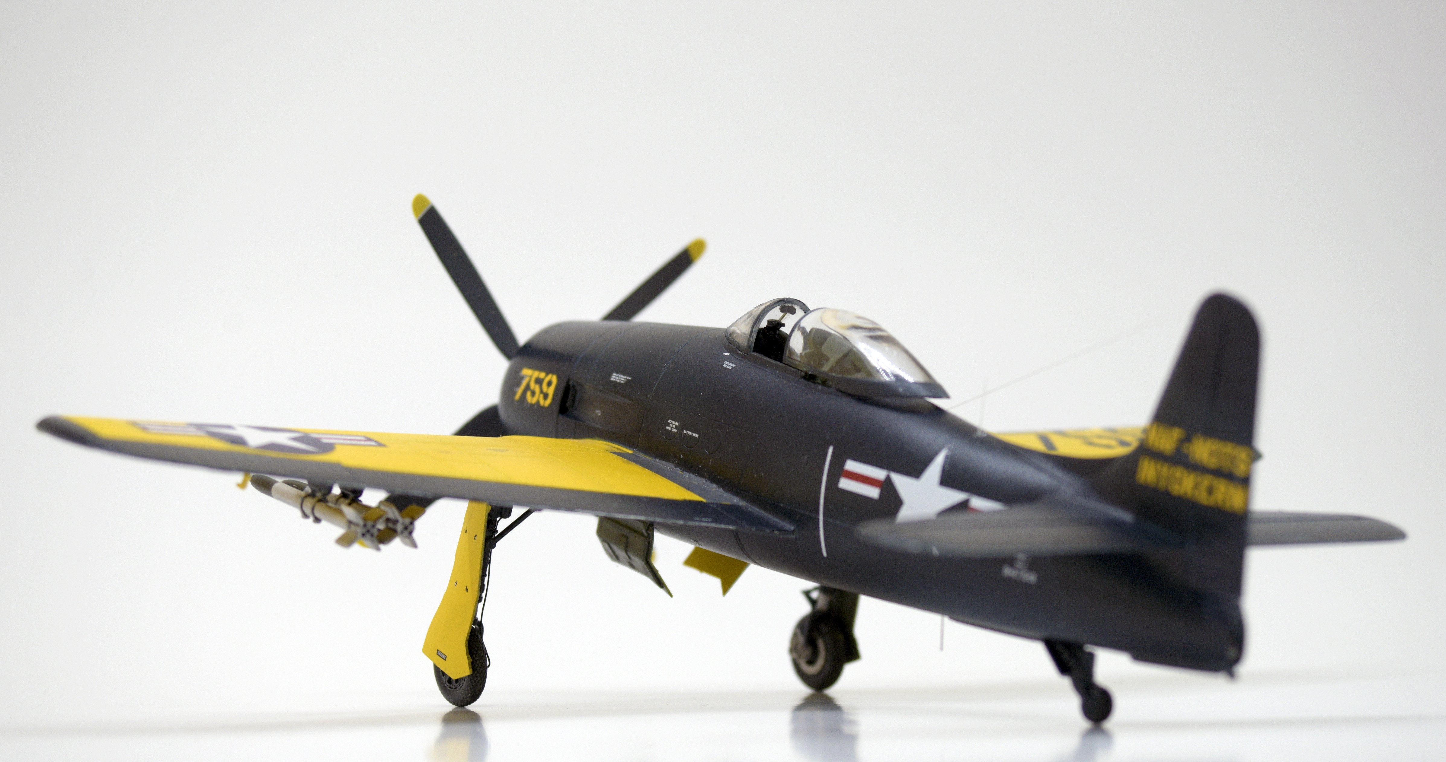
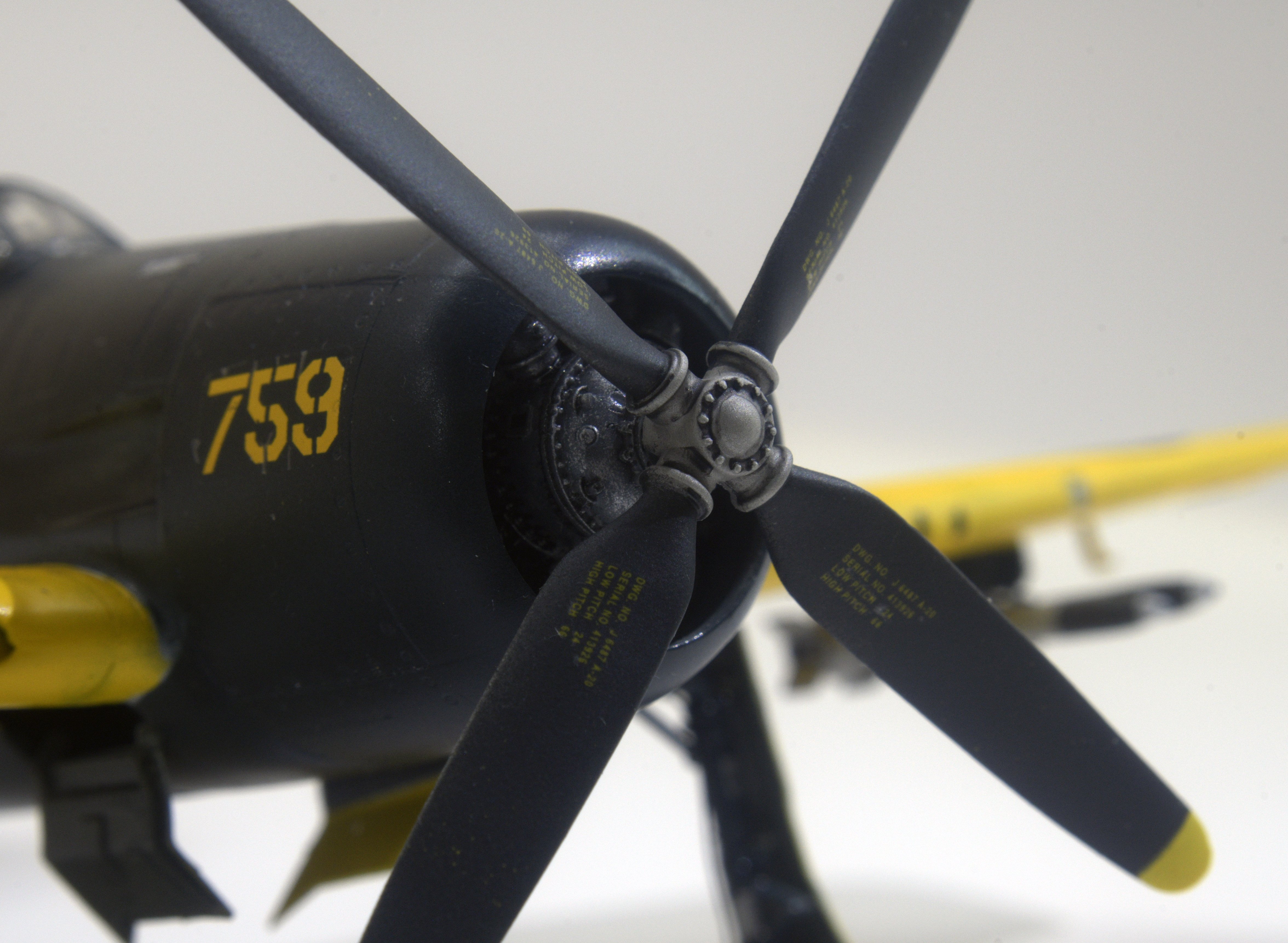
I started this project with the intention of building the 1/48 Hobby Boss F8F-1 kit. But early in construction, I ruined the lower wings trying to install resin gear bays. I ended up pulling a Hobby Craft F8F-1 kit from the stash, and elected to use the Hobby Craft cockpit, wings, stabilizers and fuselage, and the Hobby Boss prop, cowl, landing gear, gear doors, canopy rear deck and roll-over brace. I used markings from Starfighter Decals that depict an F8F-1, Bureau Number 94759, attached to the Naval Air Facility/Naval Ordinance Test Station at Inyokern, Califoirnia in 1950. This Bearcat was used for HVAR (high velocity aircraft rocket) testing. Here's a link to a full build article: https://imodeler.com/2026/08/1-48-hobby-craft-hobby-boss-f8f-1-bearcat/
 3 points
 -
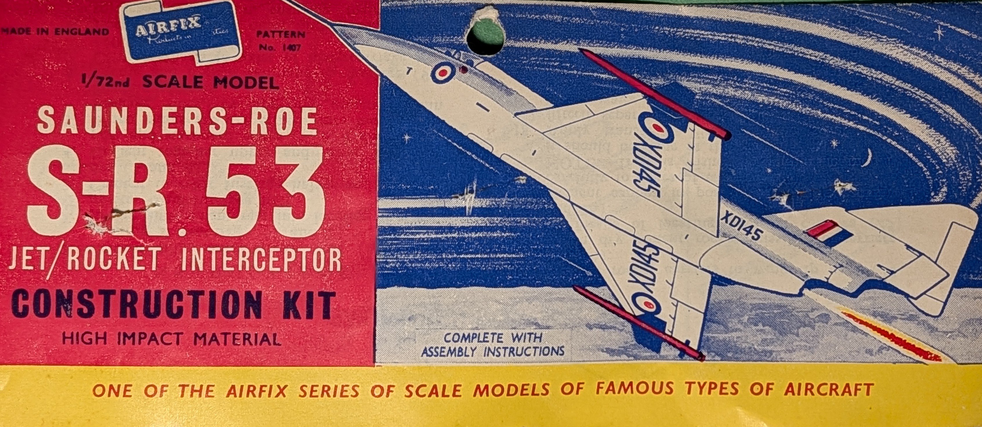
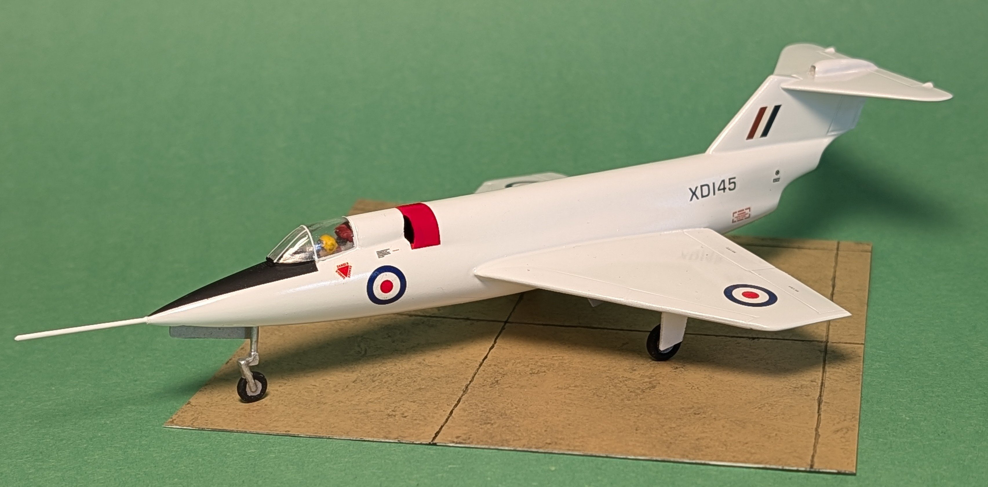
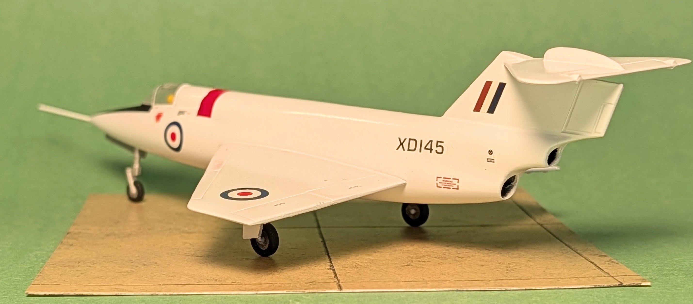
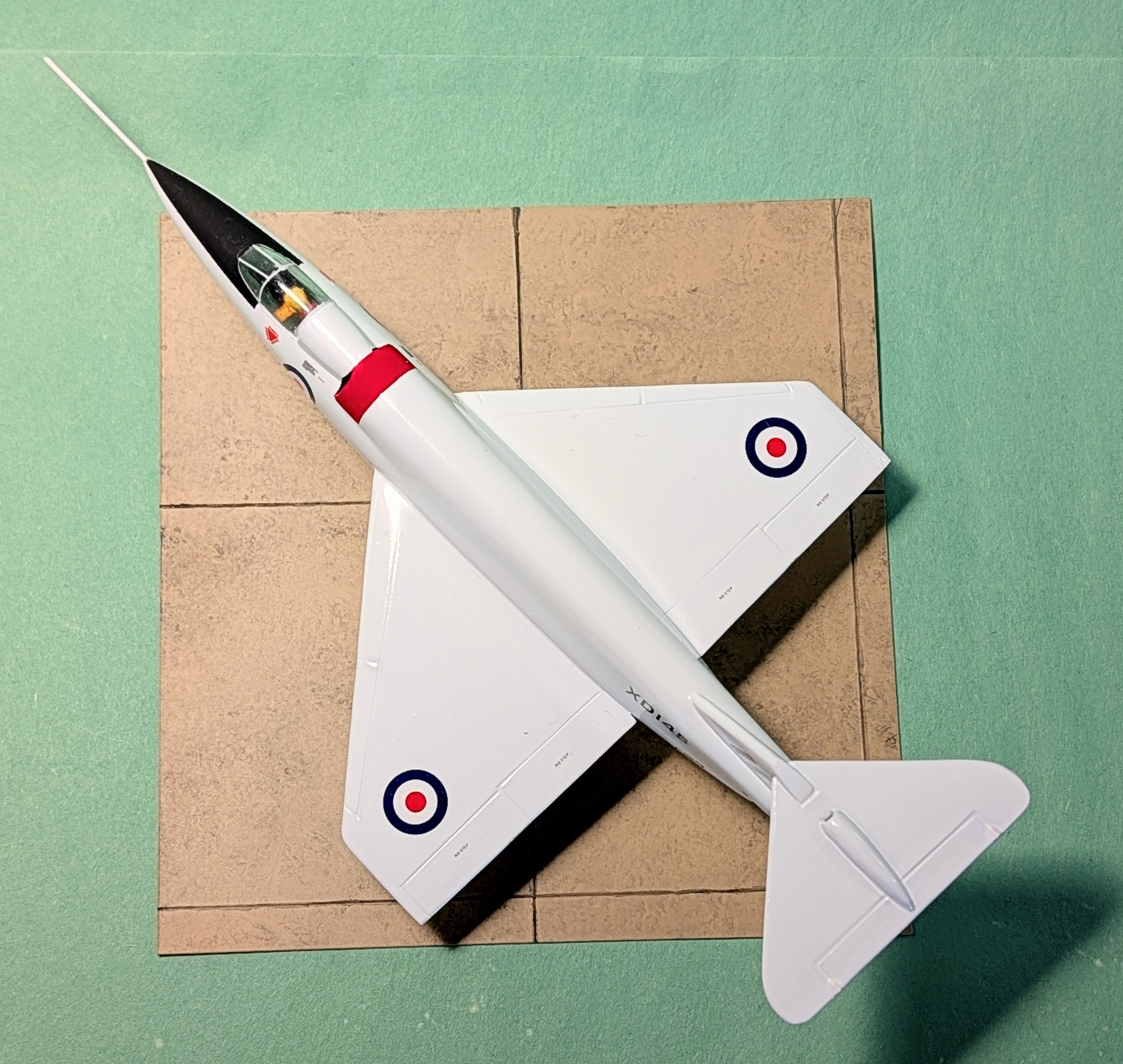
In the early 1950's the West was scrambling to develop an intercepter that could take out Russian bombers before they could nuke U.S. cities. At that time, the problem was that with the radar at hand at the time, the speed of the bombers and the climb rate of the aircraft then in service, the bombers would be over their targets before the intercepters got to their altitude. So, the search was on for an aircraft that could climb very fast to get up there to get the job done. However, none of the jet engines available had the power to do so fast enough so thought turned to using a rocket motor. But the rockets at that time did not have the staying power to last through an entire interception and not wanting to repeat the almost suicidal ME-153 concept, thoughts turned to a hybrid with the rocket motor providing the thrust to get the aircraft to altitude and then a second, jet, engine to power the aircraft through the interception and return flight. The US had several examples such as the F-91 Thunderceptor and this is the British answer to the question, the Saunders-Roe H-53. It was to be armed with the Firestreak missile carried on rails on the wing tips much like the U.S. Sidewinder often is. Despite the crash of one of the two prototypes, the aircraft proved to climb very fast and was maneuverable as well. However, more powerful jet engines and other new more capable aircraft designs were coming on line that made the concept un-necessary so the project, like those in the U.S, was cancelled. This kit dates from 1958 and was pretty primitive. It comes with two very chunky looking Firestreak missiles and since the aircraft was just a prototype I assumed they were either dummies or inert so I left them off. I just did it OOTB with extensive cleaning up including removing the trench-like panel lines one the fuselage but leaving the control surface ones. The pilot looked like the villain in the 1950's Sci Fi movie "Robot Monster" so I used one I got from the spares box. The decals were shot, so put some together from the spares box, cobbling together the serial numbers piece by piece from rub-on lettering. In the end, it produced a very pleasing looking aircraft I believe.
2 points
-
This is indeed as they say a "sticky wicket"! I'm approaching my 50th year as an IPMSUSA member and getting members to VOTE has ALWAYS been a problem. Part of it stems from our members being willing to let others do the work for them in their clubs and thus they don't view themselves as needing to be more active or interactive locally and especially nationally. And then, even if they do intend to vote, it often just slips by the wayside until it's too late to do so. However, I do think it's a problem that WE can more easily solve than ever before. 1) I know (according to the business meeting at the NATS) that IPMSUSA is about to "revamp" its website. I HOPE THAT INCLUDES A MORE OBVIOUS AND EASIER WAY FOR MEMBERS TO LOG ON AND IN! The current system, while it certainly works, just isn't that easy to find and not "intuitive" enough. Also, if you're a Chapter Contact like myself you have to be sure you're not signing in as "the club" instead of yourself. Making it easier to sign on/in is the first step to making it easier to casting a vote on line, where it's now done for the most part. 2) IPMSUSA STILL NEEDS TO INCLUDE PRE-POSTAGE PAID PAPER BALLOT POST CARDS for the members. This IS an added expense, but if you put it in the FRONT of the Journal (not bury it in the middle) with a large add page immediately behind it that says "TEAR OUT AND VOTE NOW" (and make the card RED!) as well as that page also saying "throwing this card away WASTES IPMSUSA's money which might cause a dues increase- SO VOTE!!!"; more members are more likely to vote than in the past. The members will not be able to open that Journal without having to page past it. If they still tear it out and throw it away...... then that's on them. IPMSUSA needs to remember that as a graying Society, we have many members who just will not want to go on line, log in, and vote electronically. If you want THE MOST VOTES, we MUST include a way for those members to do so easily. 3) Continue to use the Wild Apricot system to mail voting reminders to the CCs which can be forwarded to the club members. Do it once a month early on and every couple of weeks the last couple of months. 4) HAVE AN IPMSUSA VOTING MONTH! We now have LAPTOPS that can be taken to our club meetings. IPMSUSA should promote that each club have someone bring in a laptop to one of the club meetings THAT month and the club use part of their meeting time letting the local IPMSUSA members log in on it and VOTE! This may catch a few more votes and who knows, might even perk the interest of some non-members (who are being excluded) in wanting to join so they CAN participate. There may be more ideas that will help, but those are the first off the top of my head. It will STILL be like pulling teeth..... Most of our members didn't join to be a part of running anything or to be "political"; they just want to be a part of hanging around other modelers with the same interests and/or they wanted the Journal. We can certainly appeal to their "sense of duty", but then again that's never been a real vote prompter in the past so it'll take more than that going forward. I think some of my suggestions put it more "in their face" and hopefully lessen the chances of simply overlooking and forgetting to vote. Lastly, I AM NOT FOR LOWERING OR CHANGING THE CURRENT VOTING QUORUM REQUIREMENTS. As pointed out above, it puts IPMSUSA at greater risk of a very small minority hijacking the Society for its own uses. I would remind everyone that we JUST barely avoided that only a couple years ago and we do not want to set the table for any others in the future by making their efforts easier to accomplish! Gil #108032 points
-
This was my 33rd or 34th Nats I've attended since 1978. I've seen plenty of debacles and many, many excellently run Nats. I've been a Nats judge since the late '80s, was a Contest Chairman for the '97 Nats, and thus (at that time) had a hand in putting together the awards ceremony pics (slides, back then!). I say all that simply to point out that I've seen the Nats from the outside AND the inside and know how much work it takes to host one. The Ft. Wayne folks (along with their IPMSUSA counterparts in registration and judging AND all of the volunteers) can take credit for THE BEST IPMSUSA National Convention in my experience! From registration when I arrived right up to the Awards ceremony that closed the show they ran things smoothly and seemingly seamlessly, and did so while also dealing with record attendance and model counts in both the contest (3110) and the Tiger Meet (over 1000). I also want to commend their choice to break with tradition and simply SHOW all of the pics of the Nats winners at the awards show without announcers telling us what we were looking at. It not only sped things up, but this format means IPMS no longer needs to find the next "Bill and Aris" show each year. I also agree with awarding the Juniors earlier in the afternoon in order to give them their recognition at an earlier time as well as more among their own peers. All I would add is to show the Junior Best Ofs and Junior Grand Award winner (10 or so pics, less than 2 minutes time) to start the regular awards show in the evening. Ft. Wayne has set a very high bar as well as establishing some new ideas that I think should be carried forward. They deserve all of the praise you may have read elsewhere, but I wanted to add my personal thanks and kudos to a job so very, very well done! Gil Hodges #108032 points
-
I have to agree with everything you said. This was my 10th National Convention (and likely my last), and probably the best in my experience. My only complaint was the absence of Andt's HHQ. That's on him, though. Great seeing you!2 points
-
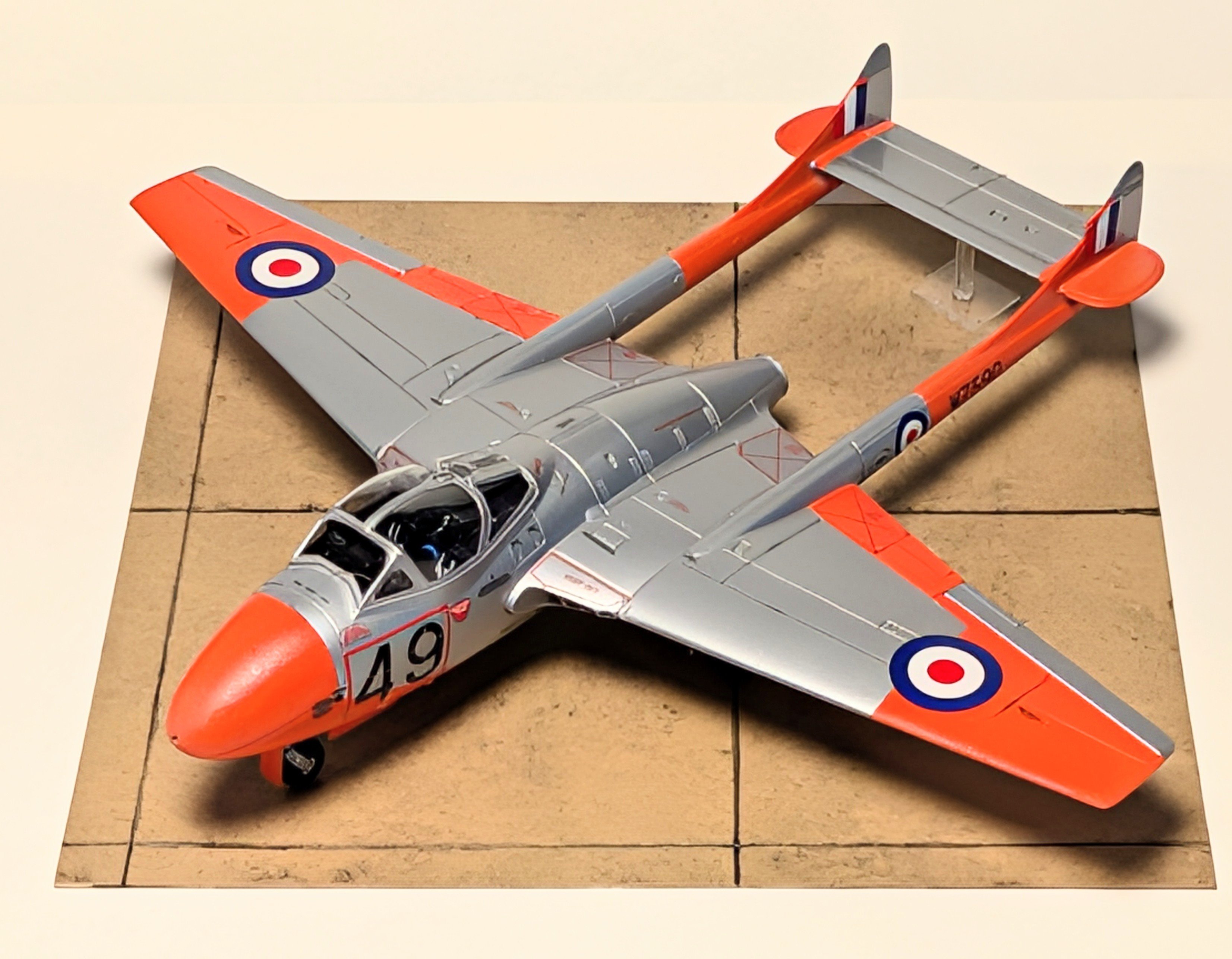
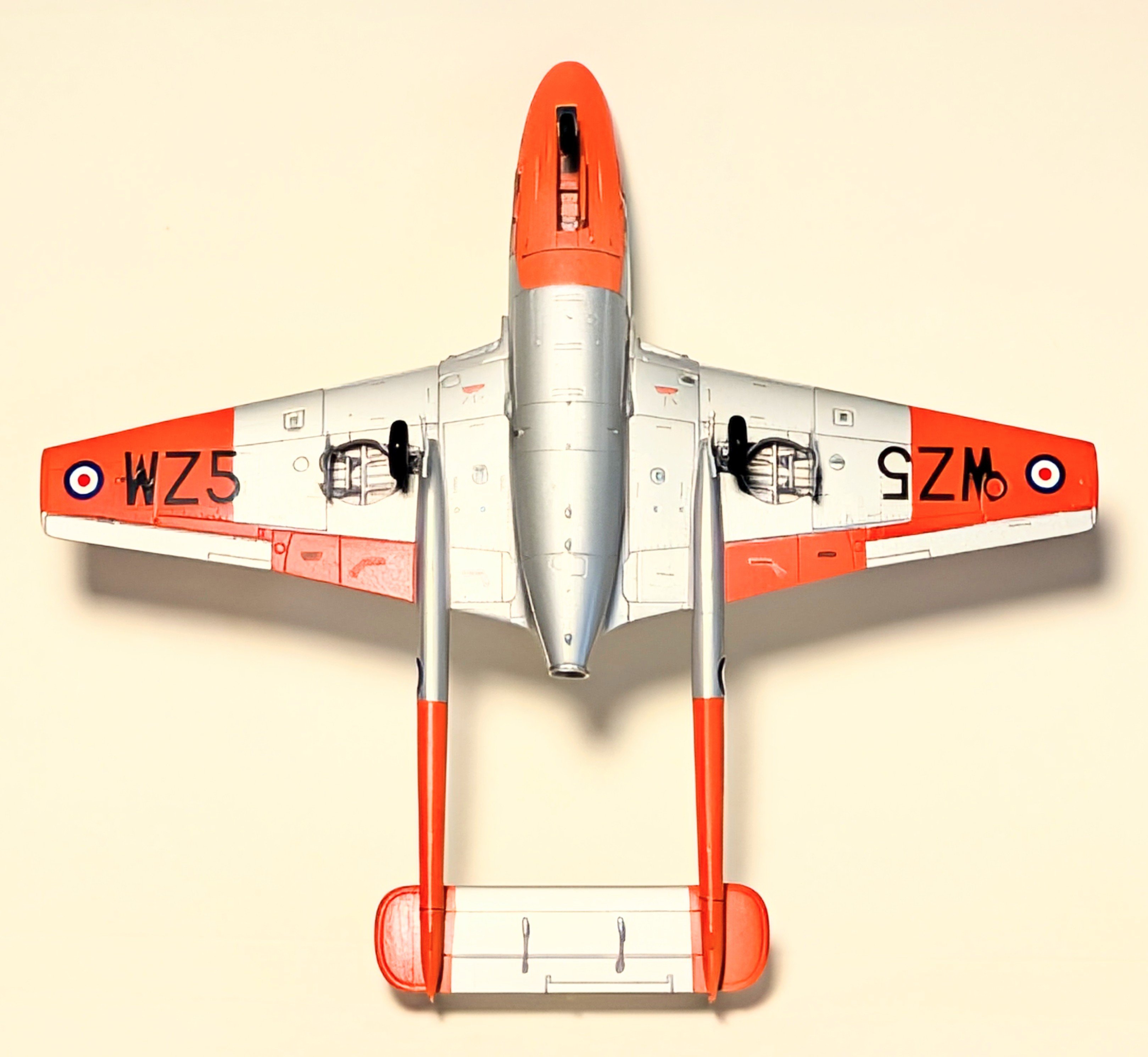
A friend gave me some models that a friend of his had already started. In this case, the center "pod" was together, the cockpit done and the canopy was in place. It sat on my shelf for a few months (years?), but being between projects, I dragged it out to fiddle with. One thing led to another and, voila, I got it finished. That's Tamiya AS-12 silver and Testers Florescent Orange. I used the Testers because I didn't have access to the Humbrol color that was called out and it was as close as I could get. It may be a little too light, but, meh, it's just going to sit on my shelf. After having done some of these new Airfix kits I have learned to go slowly, study the instructions and do what they tell you when they tell you. If you don't, well, bad things can happen. In this case the only really bad thing was the previous owner hadn't put any weight in the nose so it's a tail sitter, thus the clear plastic prop under the tail. This little bugger has somewhere north of 60 odd decals on it, some literally the size of a pin head. Tedious work, that. In the end, it turned out pretty nice I think.
2 points
-
I first read Robert Johnson’s autobiography when I was in grade school, probably when I was around 9 or 10 years old. One incident in his story always stuck in my mind and that was his near fatal mission of June 26 1943. On that sortie his aircraft “Half Pint” was badly shot up by FW-190s of JG-26 during a bomber escort mission. His description of the ordeal in the book has had me wanting to build a model that P-47 of his one day, but it was a P-47C, and nobody at the time was making kits of the P-47C, only D’s, M’s, & N’s. But then SuperScale Decals released a set of decals for all of Johnson’s P-47s, and Cutting Edge released a P-47C conversion cowling for the Hasegawa P-47D Razorback. I bought all of the above and eventually started the project, but then it was sidelined when I encountered some warping on the fuselage where it connected to the lower wing behind the engine. So it sat for many years on the shelf of doom until I recently decided to do knuckle down and finish this one up, no matter what. Without further elaboration, here is my build of “Half Pint”, as it would have looked, before setting out on that June B-17 escort mission. Decals are SuperScale, paints used are primarily AK Real Colors and Tamiya Acrylics. Thanks for looking, comments and critiques are welcome1 point
-
Today I can show two more helicopters I finished this month. The first one is the Mach 2 1/72 scale SM-1/300 helicopter: It's rather crude, but it's the best I can do with a Mach 2 kit. They truly define "short run" kits! And next is the Revell 1/72 scale US Coat Guard HH-65 Dauphin, my first Coast Guard helicopter: I did my best with this too, but it seems lately, I'm not achieving the best quality that I can. I'm guessing it's because of some of the health issues I'm going through. At least I'm still building though. Thank you for looking in, comments are welcome.1 point
-
They both look great! That Mach 2 kit really came out nice.1 point
-
Well this stinks. I agree with Ron, Patrick and Nick. How about some info as to why.1 point
-
Hi, I would also like to shoutout David Willis who has been behind the scenes for the last several years handling the account registration requests. His work has been largely been un-recognized, but its been a great help... Eric1 point
-
If I live to be 100, I will never understand why organizations make such decisions as this without any explanation at all. Managers never seem to learn that silence always encourages counterproductive speculations to fill the information void. If there is a good reason for this decision, there should be no reluctance to provide it. If it is for a bad reason, perhaps it shouldn’t be made in the first place! Nick Filippone1 point
-
I've read the minutes but no reason why is given. I'm not arguing, just asking.1 point
-
I'm getting close to completing the Young Frankenstein series with Inspector Kemp. He represents the Lionel Atwill character of Inspector Keoh. For YF, the Inspector is played by Kenneth Mars. For the kit the likeness is excellent as with the rest of the models. The bust comes in 3 parts - the bust, base and arm. It also comes with some darts and a dart board to replicate the humorous scene. The first step is actually- what colors am I using? I was able to find a colorized version of the movie that shows him in a black hat and a very dark blue uniform. The ornaments on the hat are gold, but silver on the jacket. My first go round with paint (before I found the images) had him in blue with blue. But you'll at some point the hat changes to black. I also jumped back into an old Citadel shade for a base flesh color, and a first highlight. That's where I'll leave him for today. Check back. Thanks for looking. Moving on I started adding color to all his ornaments and such. First step was to mask off the sleeve to to put the silver bands on. Nice and easy until I took the masking off - then tragedy! The problem here is that I had to mix that dark blue color. Let's see how much paint I have to waste to get that color back. Yes, a wet palette should have been used. 😕 Taking a break from the good I turned my attention to the base. I suddenly remembered the old way model railroaders used to do their mountains just putting wash blobs of color all over until things blend. Right down my alley, and it didn't come out bad. After that I start with the darts. On that colorized version I'm guessing they had or saw what antique darts looked like. so I mimicked that. I also painted the dartboard, but since it's a pretty large accessory, I'm deciding to leave it out of the display. Doing a double check I was happy enough to call it done. Thanks for looking.1 point
-
It's been a slow month for me modeling-wise, but I did get this one done so far: Mach 2 1/72 scale Australian Navy AS-350 Squirrel: There are at least two more helicopters that might get finished this month but for now this is it. Thank you all for looking in, comments are welcome.1 point
-
First I'd like to thank you for following this post , it's quite appreciated ! 1/48 LOCKHEED T-33 SILVER STAR (TESTOR) (AUG 26th ) Today I done the dry-brush on the fuselage interior , and start working on an pallet to position the fuselage on ! If you like to follow the complete WIP on this project , I have set up an GOOGLE page, just follow this link .. https://photos.app.goo.gl/mCtpo97pwYCFaYE39 If you like to view the complete STASH PARTS done so far ,just followthis GOOGLE link .. https://photos.app.goo.gl/NtNSgh1zJgx9jRSx5 Enjoy ! Jmarc
1 point
-
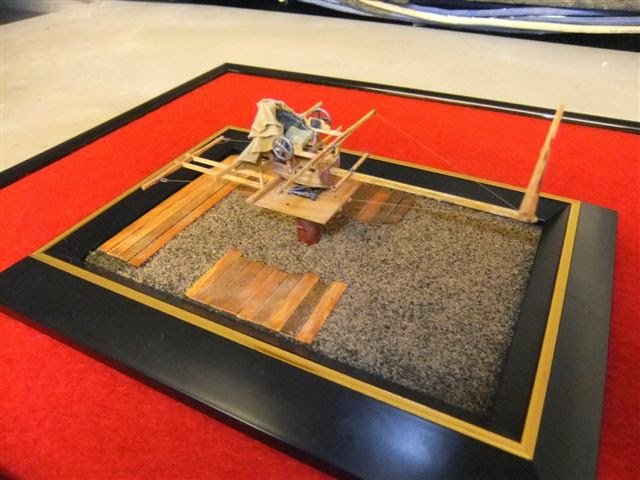
Hi ! Here another project I have done in the past , of course it's scratchbuilt , if you like to view more pics of this prject , I have set-up an GOOGLE page for it, just follow this link: https://photos.app.goo.gl/yuQutHmNnZNFEhdY7 Enjoy ! Jmarc
1 point
-
LLLLLLLLLLLooking good !1 point
-
In addition to my current P-47 project, I’ve also been plugging away at this old project, the old Tamiya German Motorcycles kit, along with the one that came with the Flak 36 kit that I built many years ago and never finished. So as paint or glue was drying here and there, I have made some progress on these bad boys. Recently I finally finished basic paint and decals Today I did some heavy duty weathering. I was not quite intending on such a heavily weathered look, but in the end I decided to run with it… I still need to do a bit more painting and weathering on the riders to match the bikes dusty finish, and then finish painting then add their rifles 😉1 point
-
So my latest batch of progress photos… During the week I applied Tamiya Liquid Panel Liner then cleaned it up. Afterwards I then airbrushed on a flat clear coat A couple of days ago I replaced the kit gun barrels with some Albion brass tubing of an appropriate diameter and cut to the proper lengths, and then glued them in place. Today I painted the gun barrels with Metalizer Steel I also today finished painting the exhaust stacks and turbocharger exhaust shroud, among other small details That’s all for today… finish line is approaching rapidly!!!1 point
-
It's a re-box of the IMAI kit from the early 70s or late 60s. Motorized I think. I wonder if the Nitto or Arii kit are off spring of this kit?1 point
-
Here's the kit box as shown on another forum.
1 point
-
Coverage of the 2026 IPMS Nationals in Fort Wayne, Indiana - Dioramas, Juniors, and AircraftView the full article1 point
-
Gil, thanks for the kind words. We've been using a new system for three years now to build the slide show, and it's getting refinements each year. Because of the Model Registration system, we just download the data for entries. No tedious typing names and descriptions. The biggest challenge for the slides now is catching errors. This year we took two passes on Saturday morning and still missed a few pictures that were wrong. Your attention wanes looking at 600 slides. We may even be able to use AI in the future to help with that. Cheers, Jim Coatney, #468151 point
-
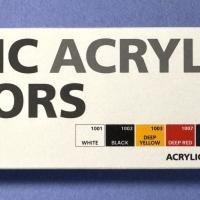
In addition to producing some wonderful model kits of a plethora of subjects, ICM has also added a line of acrylic paints, some of which have been reviewed here in the past. This set contains basic colors, which are good for adding details to nearly any subject, and can be mixed as needed to create any color you can imagine. Modelers who are familiar with water-based acrylic paints will have no issues with using this set. View the full review
1 point
-
My congratulations to Ft. Wayne on a job well done. I have some experience with National Conventions on several levels and from what I saw it ran flawlessly. And even if there were flaws, the attendees didn't see them so that means they were handled well. As the Brits might say (sort of), "Well done, that man, Ft. Wayne".1 point
-
Thank you Gil! I wasn't aware of it either till I picked it up at Brookhurst on their 'pre-owned' table in the back. That would be cool if someone did. Maybe I'll play around with some artistic license and add some nose art with that name....1 point
-
First I'd like to thank you for following this WIP , it's quite appreciated ! LOCKHEED WV-1 CONSTELLASTION in 1/48 (AUG 14th ) ..Today I continue reviewing the joints and panel lines of the fuselage ! If you like to view the complete WIP on this project , juts follow this Google link : https://photos.app.goo.gl/GZvfX8dsdnYnsQ2W7 Here a pics of both projects Enjoy Jmarc
1 point
-
iFrst I'd like to thank you for following this post ,it's quite appreciated ! BOEING INCITUS MQ-27 / CU-169 SCAN EAGLE 1/48 ( 3dPRINTED +ADDITIONS) (AUG 14th ) Today , I continue working on the last details ! If you like to view the complete WIP on this project , just follow this Google link : https://photos.app.goo.gl/jrWyBiNZSJHCUknZ9 If you like to view all the DRONES I have done so far in 1/48 , just follow this link: https://photos.app.goo.gl/mjGm69hDKYaDuFNX6 Enjoy !
1 point
-
First I'd like to thank you for following this post , it's quite appreciated ! 1/48 LOCKHEED T-33 SILVER STAR (TESTOR) (AUG 14th ) Today I continue working on the inner structure ! If you like to follow the complete WIP on this project , I have set up an GOOGLE page, just follow this link .. https://photos.app.goo.gl/mCtpo97pwYCFaYE39 If you like to view the complete STASH PARTS done so far ,just followthis GOOGLE link .. https://photos.app.goo.gl/NtNSgh1zJgx9jRSx5 Enjoy ! Jmarc
1 point
-
Thank you Jean Marc. I do need to organize that workbench better. There's too much clutter on it. I just tend to clear out an extra space when things start filling up my workspace. Stay tuned, more to come.1 point
-
Thank you Keith! It's not my first one either. I also built a Ka-60 Russian "Dauphin" some years back. The grey is Model Master Aggressor Grey. It might not be accurate but it was the closest I could get to that color.1 point
-
Thank you Jean-Marc! It's been awhile, given all that has been happening, but now I have a chance to start another tour. I have a few continuing projects and started a few more. So with that being said, let's all board the trams and head out to the Hangar to start. Here in the Hangar, we have the first bay holding the C-46 that I got from a friend that bought it in a thrift store. It's been languishing a bit, but now I have the new paint on it and started adding the landing gear and propellers: Some substantial pieces are missing from this, such as the main wheels, tail wheel and propeller hubs among others; so some rather extensive artistic license will probably be employed here. Moving on to the next bay, we continued to work on the extensive and highly detailed main landing gear bay for the An-225. After massive effort, frustration and persistence, the final struts were installed: Later some additional parts were added and the roof of the landing gear bay were glued in place: That was enough for now, believe it or not, that landing gear bay is still only half built. Moving on to the next bay, there is a new project started. It's a civilian version of the Mi-1 from Mach 2. It is a difficult kit to build to say the least. First step was the cockpit, which surprisingly had only one pilot seat and a bench in back for passengers: And yes, they molded the instrument panel in clear; why I do not know. Surprisingly, the fuselage went together well and I was thrilled that it did: Later additional detail parts were added to the fuselage, and the main rotors were built. They had such delicate connection points that it took forever to get glued right. I see many broken main rotors in the future: Cockpit painting came next before starting to close this up: Finally, the forward fuselage, also molded exclusively in clear; was installed along with tail rotor, more details and a test fit of the main rotor. The forward landing gear was still too wet so it flopped over when I tried standing this up: Moving on to the next bay, we have another helicopter. This is another shelf queen that has been languishing for awhile. Frankly, I don't even remember why. So, once I painted the interior, I started the process of working on this some more: I closed this up inside the fuselage and got ready to add more parts later once it dried sufficiently: That completes the Hangar portion of the tour, now on to the Shipyards. Here in the shipyards, several new keels were laid and further progress was made on at least one project. Starting in this first slip, we had the Skipjack receive her main mast and boom: Here's a more detailed shot of the deck, showing the details and wash effect applied to the parts on deck: Later this thing fell on the ground and several parts went missing, I recovered and replaced most of them but the one part that had been giving me trouble all throughout this build is still missing. I did get the smaller boat added to the davits on the rear, while the second boat had some detail touch-ups started: Also, one of the bowsprit parts went missing; I might just rig the forward sail on without it. I'm just tired of this taking space, especially with the mast on so I'm just gonna do what I can to get it over the finish line. In the next slip, our first new project is this PT-73 from McHale's Navy. The rear bulkhead was finished up and added to the main hull, then the deck was glued down. That's as far as I got on this so far: I did get more done on this next project I started in the next slip. This is the old Lindbergh SS Clermont steamship that I got at a local shop. First I started with the main boiler: Later all the linkage was done for the main paddlewheels and one of the paddlewheels was assembled to place on this assembly: Those paddlewheels do move too, which is nice. After all, this was designed to be motorized, but I don't have the features I need to motorize it. I decided to test fit these inside the hull which was molded as one piece: After seeing how they fit, I test fit the main deck on top to see if there were any issues there to deal with. So far, no: That completes the Shipyard portion of this tour, on to the Motor Pool: Here in this first bay is a started railroad flatcar. I have a kit that has two of these included so I decided to get them started. This is as far as I got, in preparation for doing all the bogies: Moving on to the next bay, this Marine M46 Patton finally got the decals applied now that I found, fixed and bought them on a site that finally had some in stock: Just some additional details and weathering and that is done. Speaking of Marine tanks, in this next bay this M1A2 Abrams has been languishing for awhile now because the barrel got lost. Finally I found a metal barrel and installed it; painted the whole tank and added the upper machine guns to it: Now I just have to find the decals.... That concludes the Motor Pool portion of this tour, so on to the Garage in back where I started the Ecto-1A Ghostbusters car I got at San Diego Comicon. I've wanted this car for awhile and found it there so once I got home, I lost no time in getting it started. First was the assembly of the interior: Then I moved on to the apparently complicated equipment rig on the roof, assembling about 90% of it: I then just had to test fit everything together: How exciting! I then started painting the interior, then parts of the equipment rig and fit it all together again: After that, I had to finish the painting of the equipment rig, add more detail parts, and painted and assembled the light bars before adding them to the rig: After seeing how far I'd gotten, I painted the body of the car white, in preparation for additional assembly: While that was drying, I completed the painting of the interior so I could close this car up: I also detailed more of the equipment rig, touching up the paint and adding a few more detail parts: The bottom also needed painting so I painted it up as well: Once dry, the wheels went on: After that I returned to the body of the car, I clear coated it with gloss, added the interior glass and started adding some light bars and details: At that point I realized that this was the opportune time to add the decals. The long black and yellow decals gave me the most fits because they tended to roll up lengthwise, making it extremely difficult to lay down flat! I finally got them all on satisfactorily enough and moved on to add the rest of the decals: At that point, it was just a small matter to complete this car. And with that, our tour ends here at Maddog Manufacturing, thank you all for coming in and remember, comments are welcome. We'll see you at the next tour!1 point
-
Gloss coat applied a couple of days ago, and main decals yesterday… I still need to finish up all the stenciling….1 point
-
Today’s progress report: I went and did touch ups on the OD/Neutral Gray demarcation line, then removed the masking from the white theater ID marking areas Next up is a gloss coat on and then getting it ready for decals…1 point
-
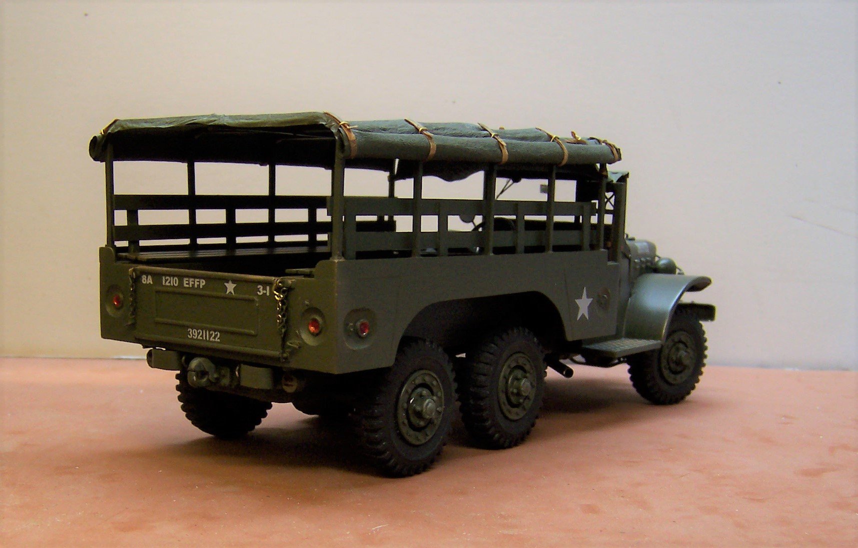
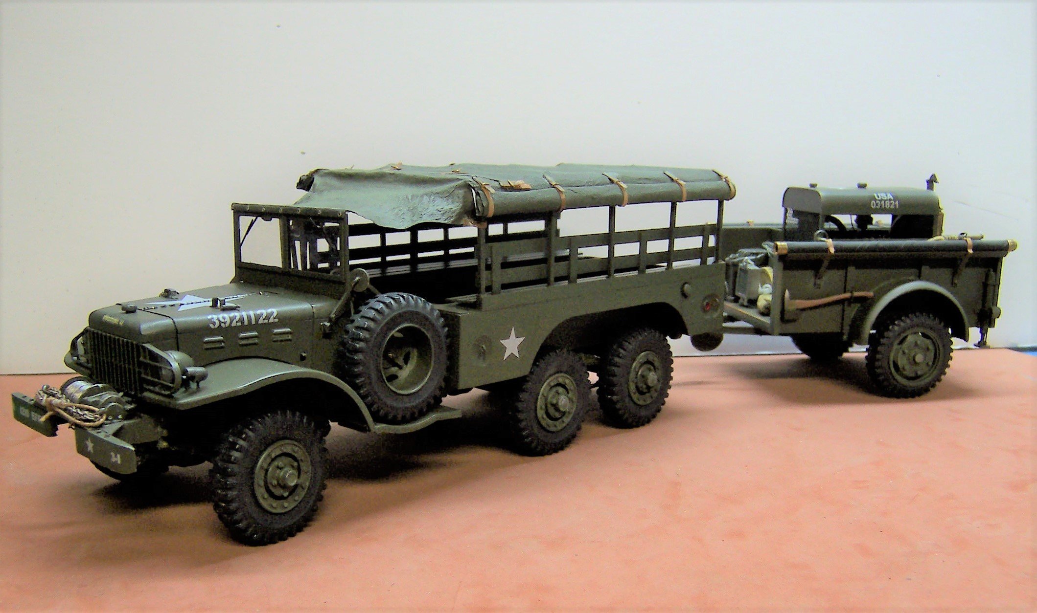
Here's a WC 63 for comparison. 1/25 scale scratch built mostly of Evergreen plastic and some sheet brass thrown in for good measure.
1 point
-
"It's Fronkenstein" "You're puttin' me on?" "No..." "Well then why isn't it Froderick Fronkenstein?" "It isn't, it's Fredrick Fronkenstein." This time around we have another bust from Pestilence Labs from 1974's Young Frankenstein series - the Doctor. The kit is a pretty simple kit consisting of the 1:4 scale bust, castle base, the "How I Did It" book, and the 2 parts of the collar that flies open during the Act Normal! scene. I would have to look hard to find any problems but one thing I would have to guess is whys does the Doctor appear to be looking down? I have a theory that I'll keep to myself, as it's an excellent likeness. (@Pestilence image) To change things up a little I decided to do the base first. It's a simple pile of stones and decided to leave them blend into the overall look - so simple grays and blacks with light gray mortar were used. Moving on to the face I added my regular pink/purple mix. While I was waiting for it to dry, I painted the book with some of V's Cavalry Red. Adding some various flesh colors I got the color I was happy with.Looking closely at his hair it seemed that he had very dark roots with some bright highlights. It's also quite obvious that they had Wilder in a lot of mascara. Finally I had to look it up to find out he had blue eyes. While that was drying I turned back to the book to add the gold lettering. Finally, it shows him in a dark (black?) tuxedo jacket with a white shirt and collar. Not wanting to use just black and white, I used V's Black Gray, and their Off-white. Just recently I noticed the buttons on his shirt were dark. I'll have to make that change. Thanks for looking. ~~~1 point
-
Thanks for the kind words! LOL agreed there's a lot of funny stuff in that movie "Can I give you a hand, sir?" "Already got one." 😂1 point
-
It takes real skill to wring as much out of that old kit as you did. Reworking the Scarf ring and the wash you judiciously applied (especially to the engine) are great touches. And I still say no one can stretch sprue as even and consistently as you can! I also got a kick out of the box art since it says "1916" but shows a Fokker D-VIII from 1918 shooting at the R.E.8! Gil1 point