Search the Community
Showing results for tags 'c-46 commando'.
Found 9 results
-
Seeking decals for the Williams Bros. 1:72 C-46 commando. I have the decals with the original (mid-1970s) release, and it has the blue of the US insignia too light. Plus, it's for a natural medal one and I want to do one in Olive Drab over Neutral Gray. I know Caracal Models has a sheet coming out sometime later, but I would like to get something sooner. I am planning to build the C-46 for a chapter display project. Any help in this matter would be most appreciated. Thank you in advance.44 Bob
-
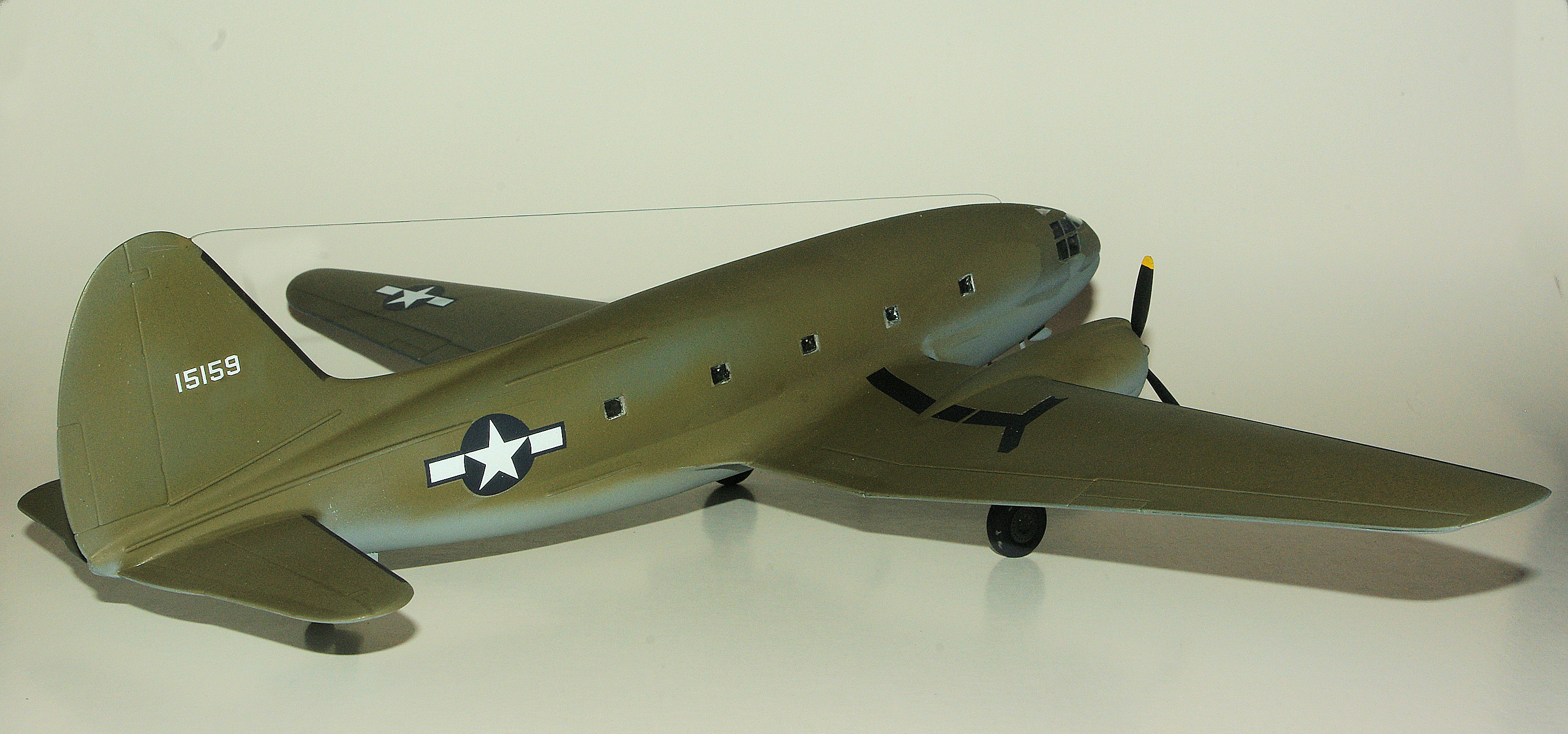
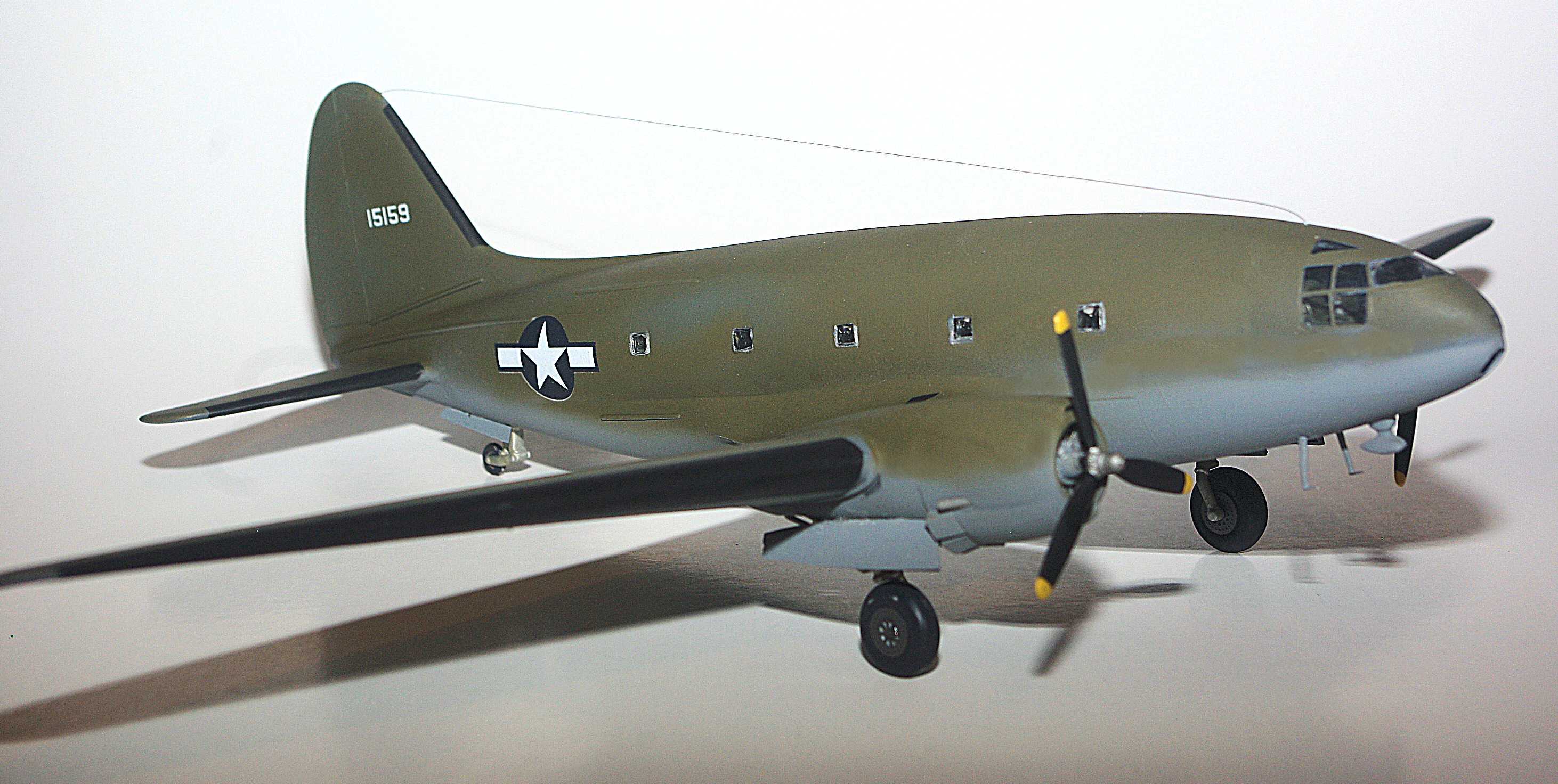
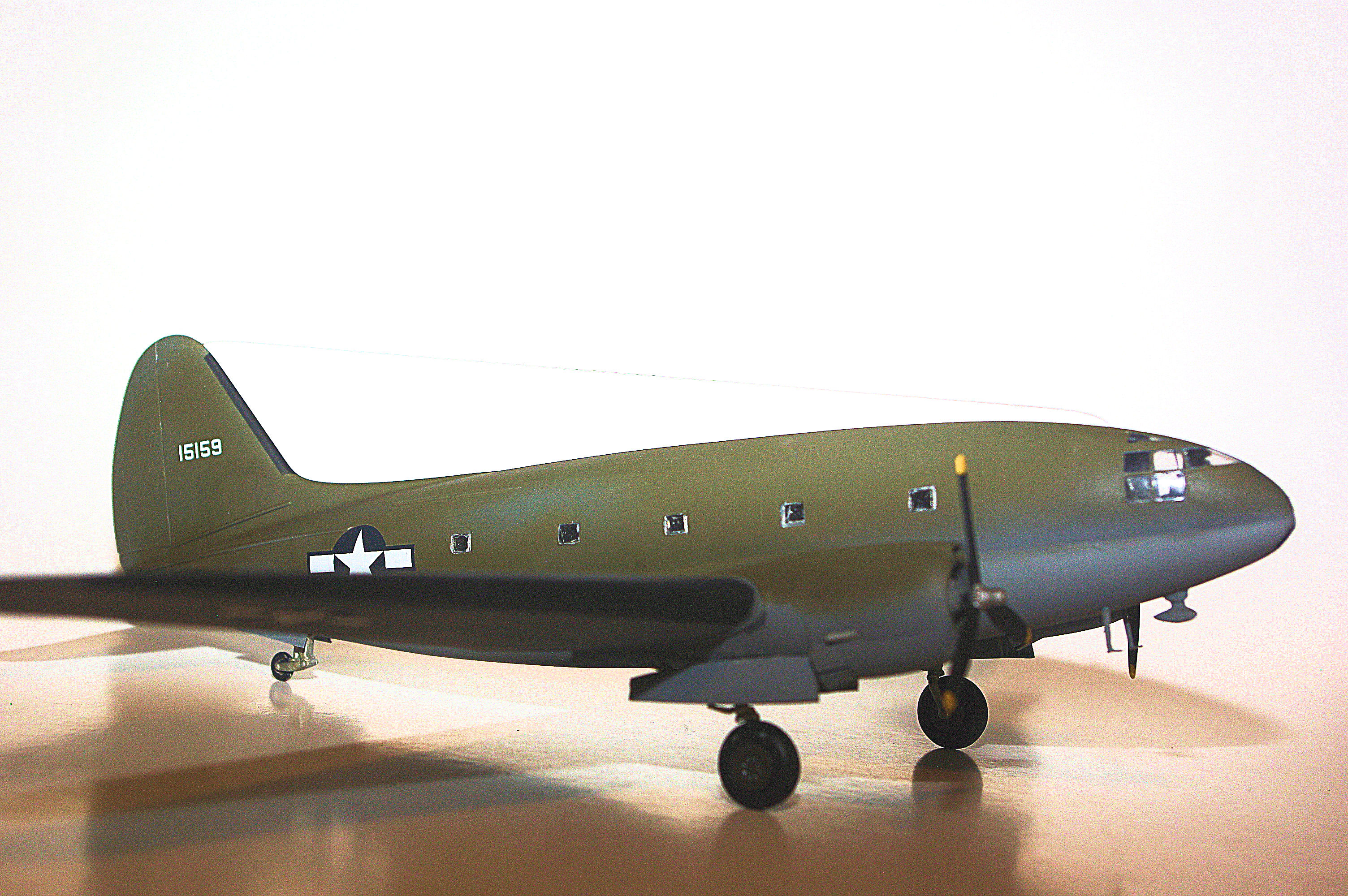
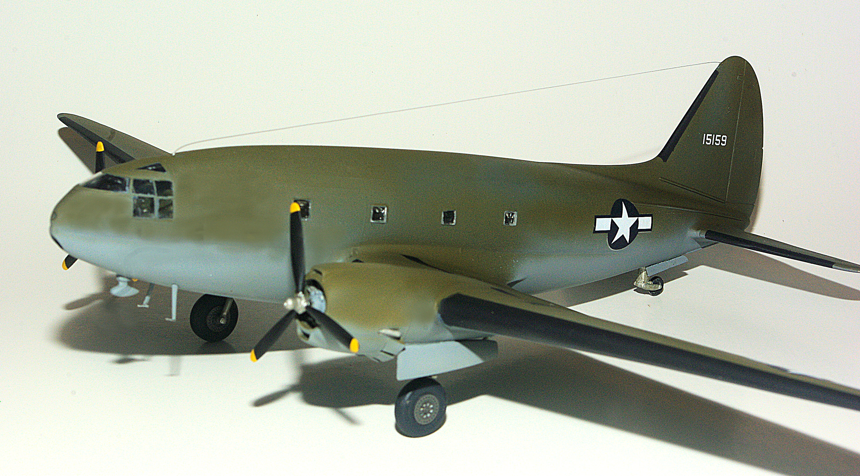
Back for the 18th and last time...at least where the C-46 is concerned. Hope you enjoy the final details and the beauty shots. C-46 Commandos displayed a dizzying variety of antenna configurations. Essentially, the only way you can be entirely accurate is to have photos of the specific C-46 that you're replicating. Since this model is a representative C-46A, I settled...with my client's agreement...on a single radio wire running from the vertical tail to the fuselage skin over the radio compartment. A #79 (.016") drill bit in a pin vise was used to drill a hole. Then a tiny bit of CA was applied to the end of a length of .0135" monofilament, inserted into the hole and allowed to dry. While I used the line that John provided, any monofilament, EZ Line or invisible thread will also work. It all depends on personal preferences or...in some cases...what's available. When you drill a hole in the vertical, it will be necessary to angle the bit slightly so that it comes out the side of the skin. Then you can run the end of the monofilament thru the hole, pull it taught...carefully...and hang a weight on the loose end to keep the line straight. Depending on circumstances, a clothespin or two will do the job, but if you need more weight, try a metal spring clip from your nearest office supply. When the line is tight, add a small dab of CA using a toothpick or similar and allow to dry. When the CA dries, all that's left to do is nip the surplus monofilament flush with the skin and carefully touchup when necessary with matching paint. And that, folks, puts FINISH to the Williams Bros 1/72 C-46A. Below are a selection of final photos. All that remains is to pack it and ship it.

-
Hi all, Just a quick note to let you know that the entire C-46A build series is now available as an e-book in your choice of formats. You can find it here. I know this post may not be appropriate here, so I won't be offended if one of the moderators deletes it. Simply wanted to make a quick mention for those who had been following the build. The next few days I'll see about submitting a copy for review along with a flyer in the what's new section.
-
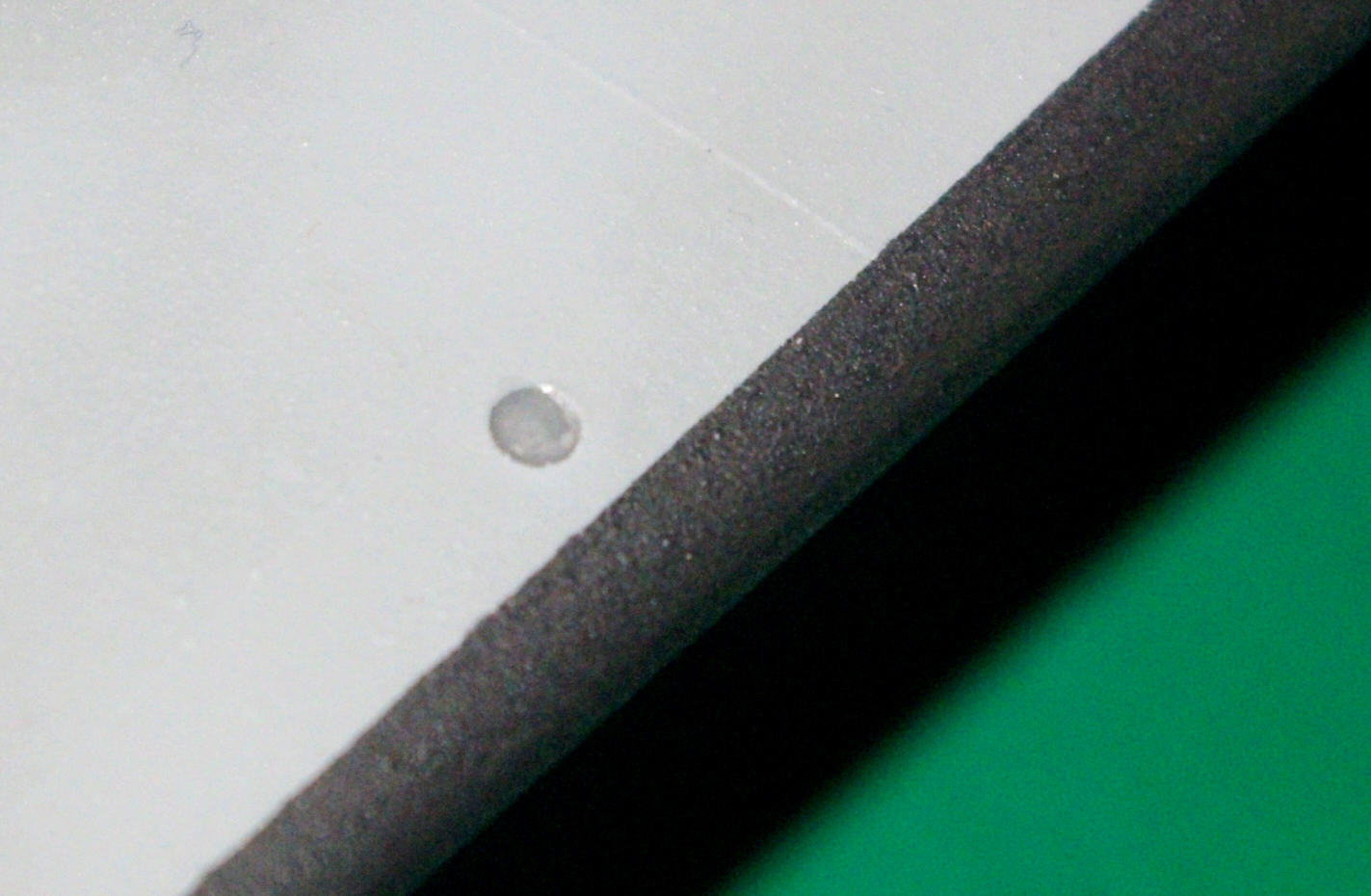
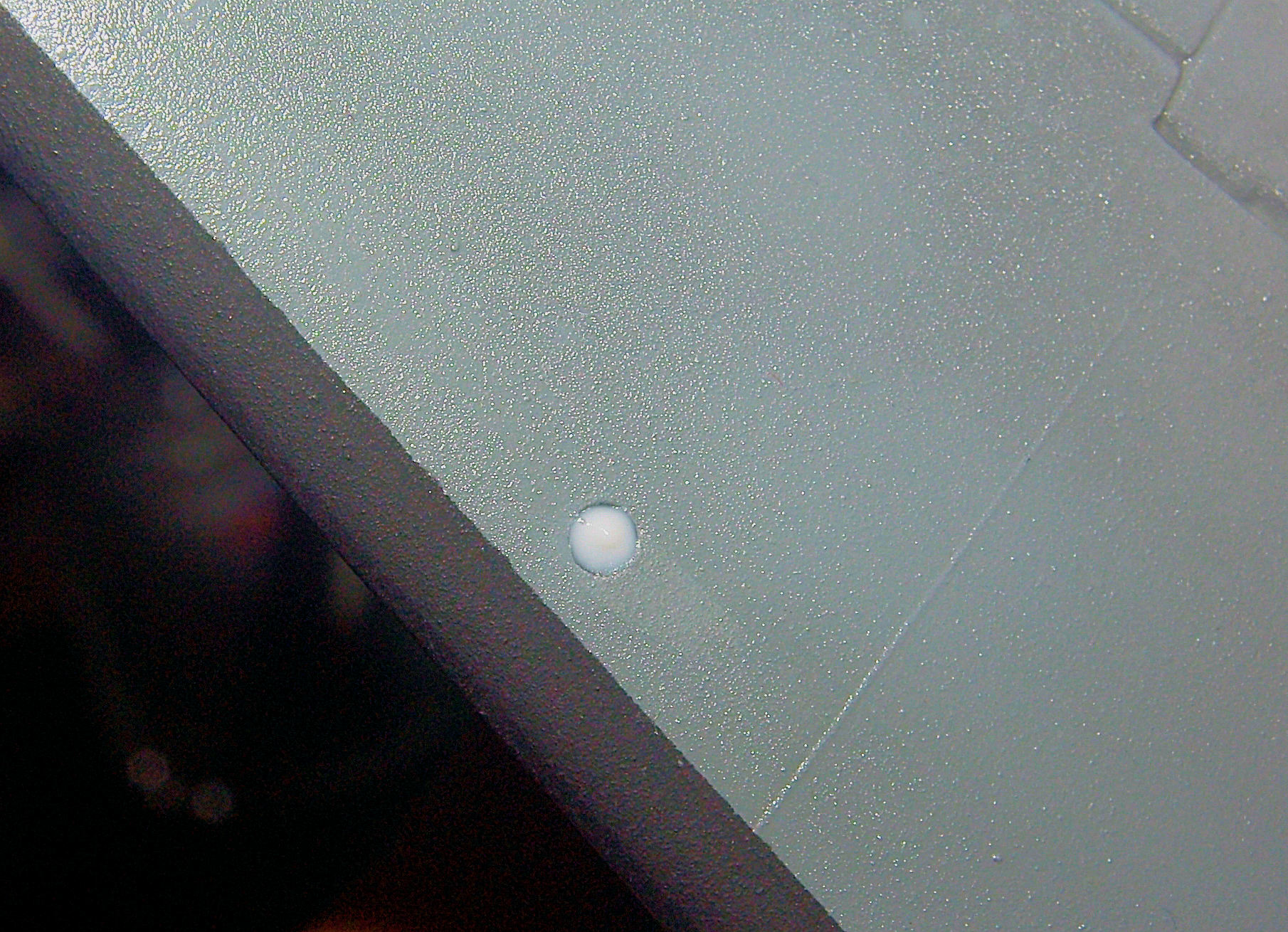
We are now at the penultimate installment. With the exception in installing the radio wire and posting beauty shots, this Williams Bros 1/72 C-46A is finished and I'm exhausted!! The nearly finished C-46A with all markings applied. For this particular scheme/time period, the only underside marking is a national insignia on the underside of the starboard wing. Though it's hard to see in this shot, due to being washed out by the camera strobes, the model still has a glossy finish from the markings being sealed with a final coat of Future. With the flat coat on and the window masking stripped, the C-46 is almost ready for the showcase. It's been a long and winding road for a very challenging kit, but the end result is very satisfying. And, as I said in the beginning, it's the only game in town if you're looking to add a 1/72nd scale Commando to your collection. So buy a kit along with the aftermarket parts and have at it. The landing light holes are filled with Gator's Grip Acrylic Hobby Glue. When it dries, a clear landing light lens will be the result. Nearly. After the Gator's Grip dried, I added a top coat of Future (PFM) to function as a final lens. By the way, this is a very close shot that makes the black deice boots look rough and grainy instead of its actual appearance.
-
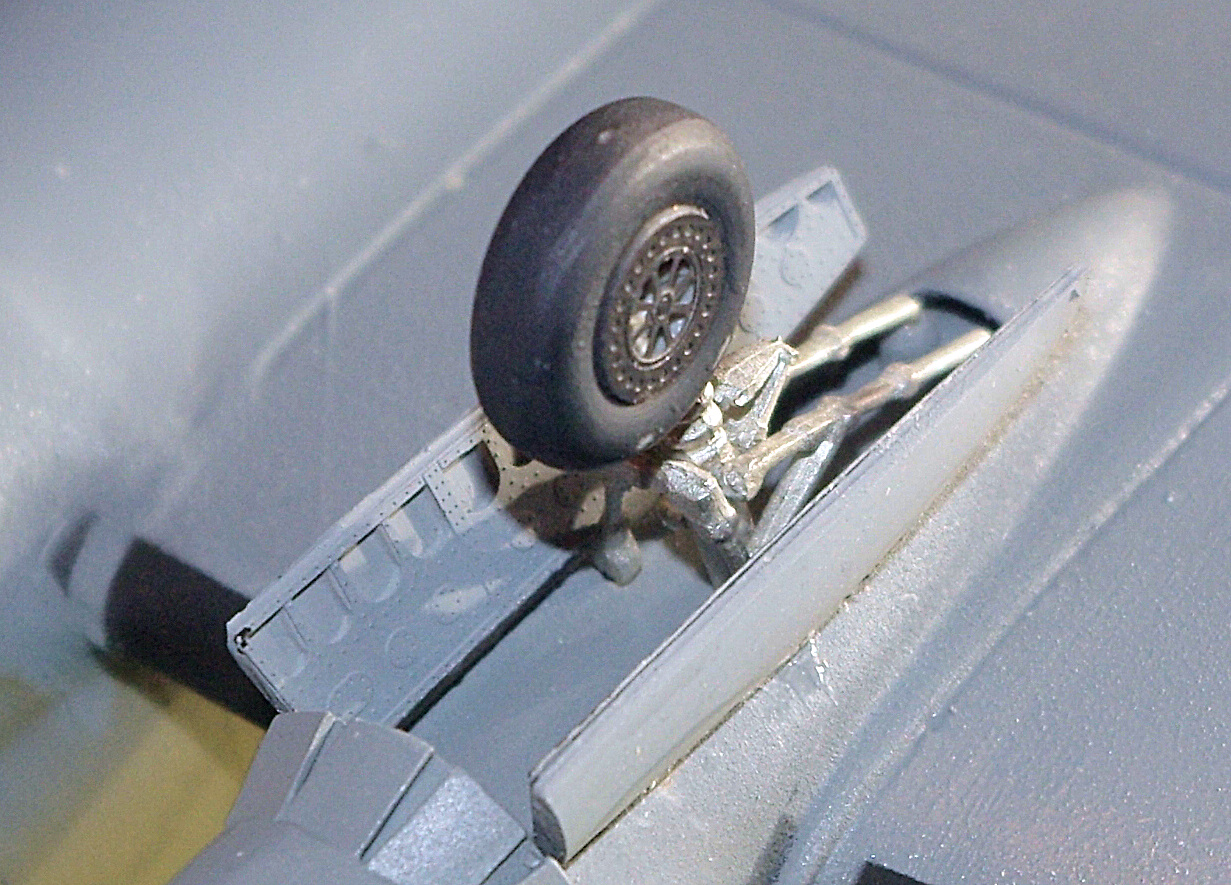
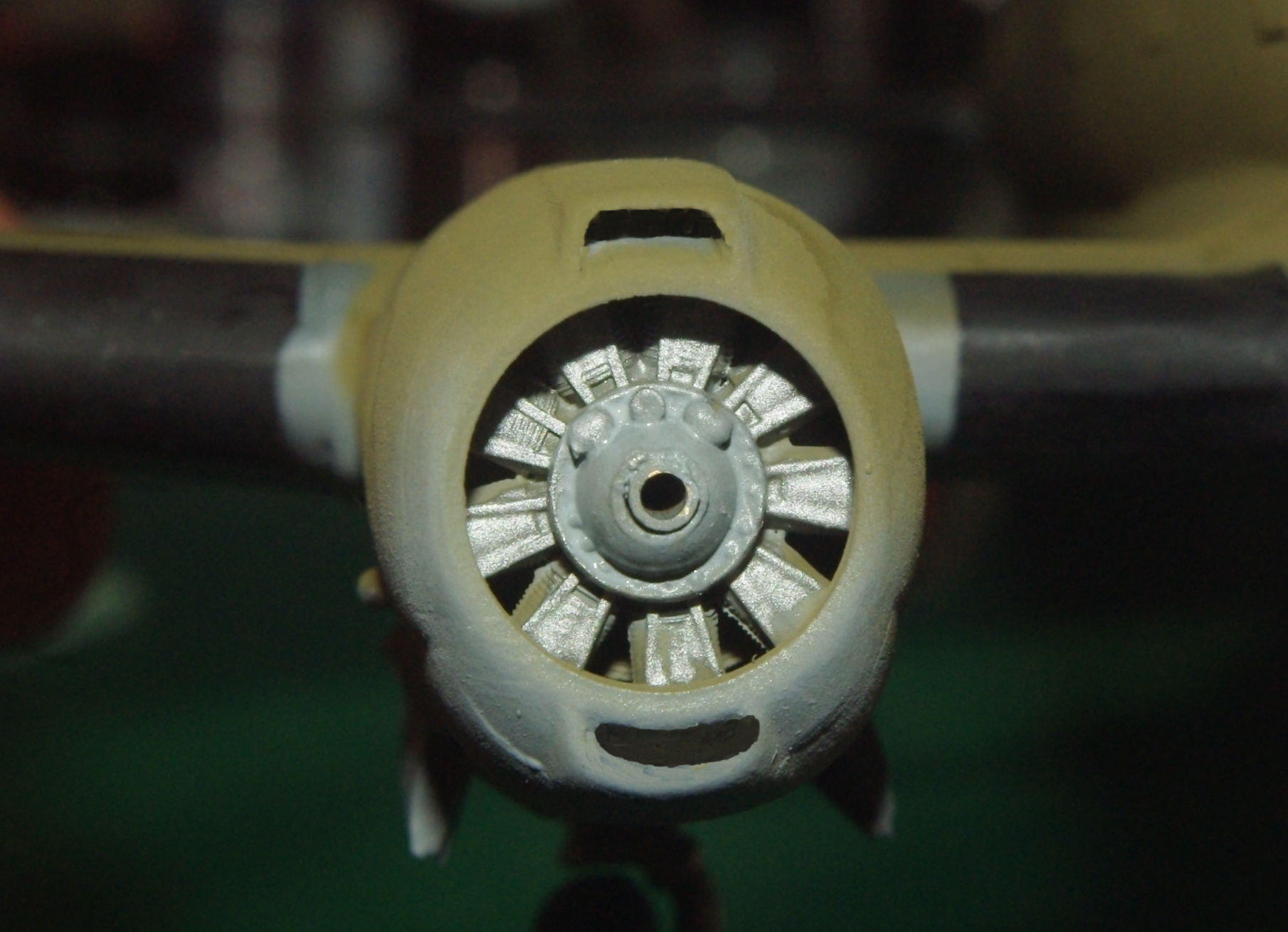
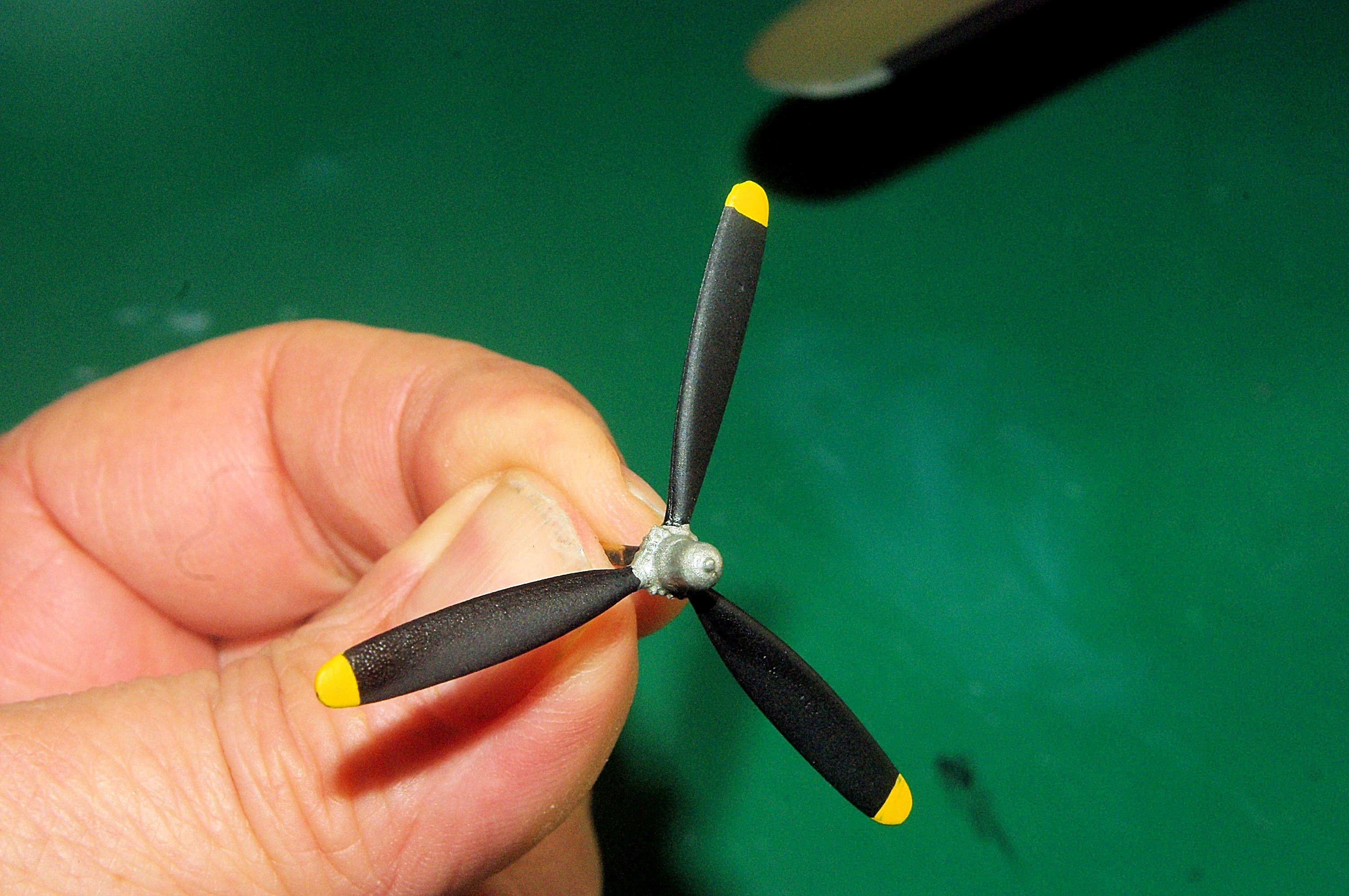
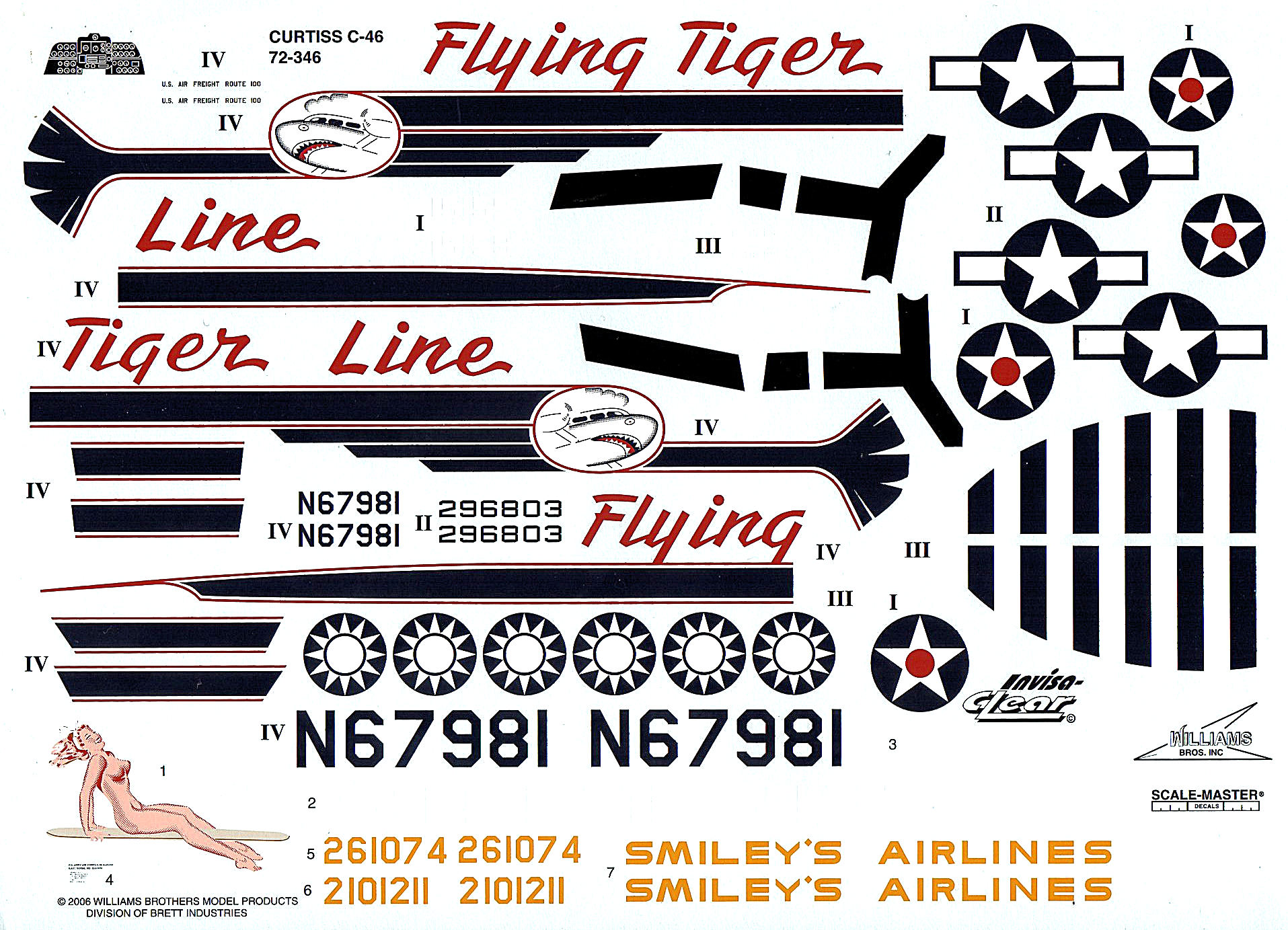
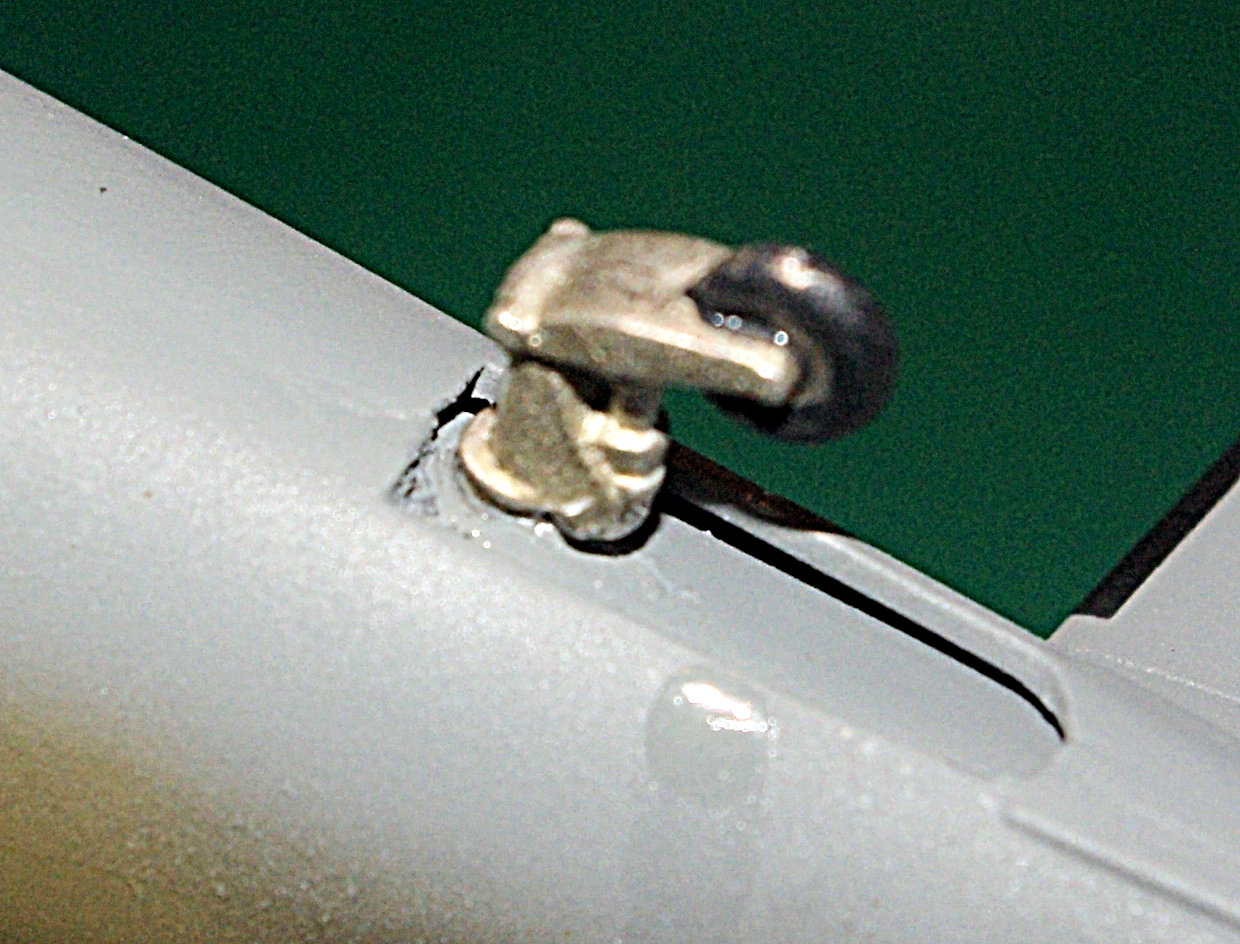
Hi all. The C-46 finish line is in sight! Here's the latest shots: The completed starboard main gear. I wound up having to apply BSI IC Gel to the mounting edge of the door, then hold it in place with one hand while applying a shot of BSI Accelerator with the other hand. Definitely tricky and I actually had to clean the cured CA on the door and try it again a couple of times before I got it right. To say this approach is tedious is an understatement of the first magnitude! The same technique had to be used on the tailwheel doors, but with the addition of tweezers to hold the doors due to their small size. The same starboard gear installation from a slightly different angle. The photoetch parts add a lot to the gear door detail and the SAC metal gear guarantees the gear won't be collapsing on you. While I did paint the engine cylinders Model Master Steel, no superdetailing was done. With the props in place, most superdetailing would be obscured. These replacement metal props really add a lot to the finished model. Model Master FS37038 Flat Black combined with Model Master Steel and Model Master FS33538 Flat Yellow produced a very nice result. Still have no idea where my client found them. This decal sheet is from the Brett Industries C-46 kit. Produced by Scale-Master, it's a state of the art sheet with markings for four different aircraft. For the subject of this model, all that was needed was the four star and bar national insignia, wing walks and some white tail numbers that my client sent from another sheet. Update from my client: The metal props were produced by a now defunct aftermarket manufacturer in the UK and were specific to the C-46. National insignia and wing walk is seen here on the starboard wing. The Solvaset seen adjacent to the model was used to snug the decals down. By the way, my ebook "How To Make Your Own Decals" covers the subject in extensive detail. You can find a copy of it at Scale Publications.
-
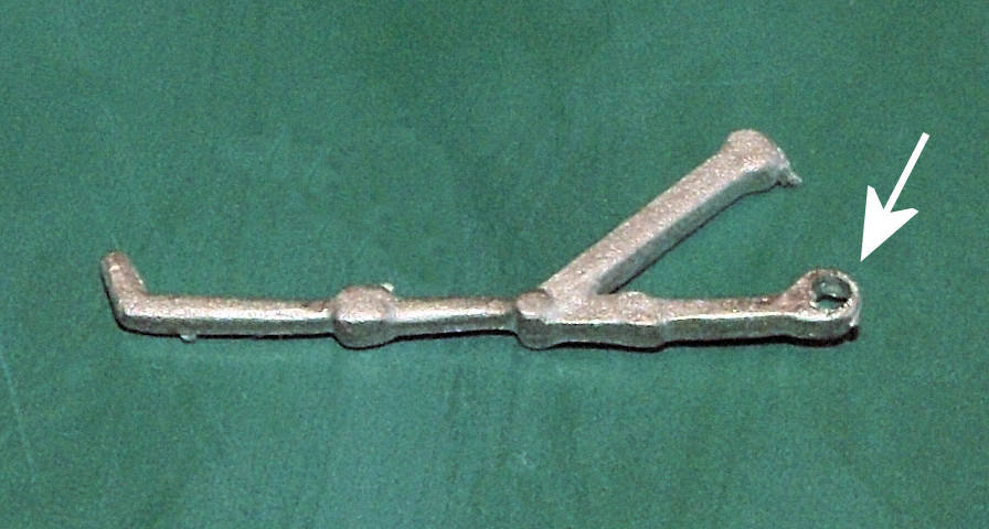
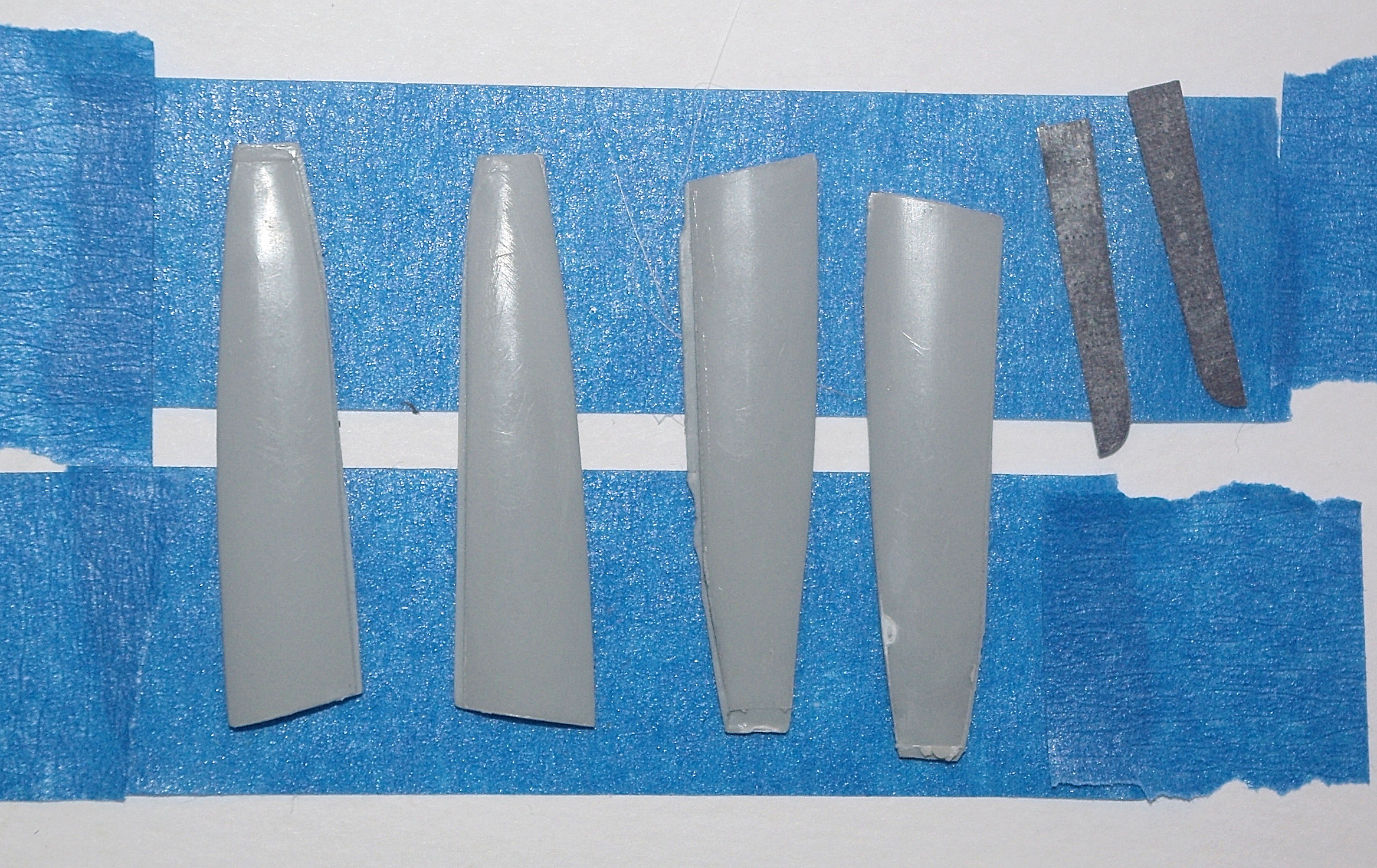
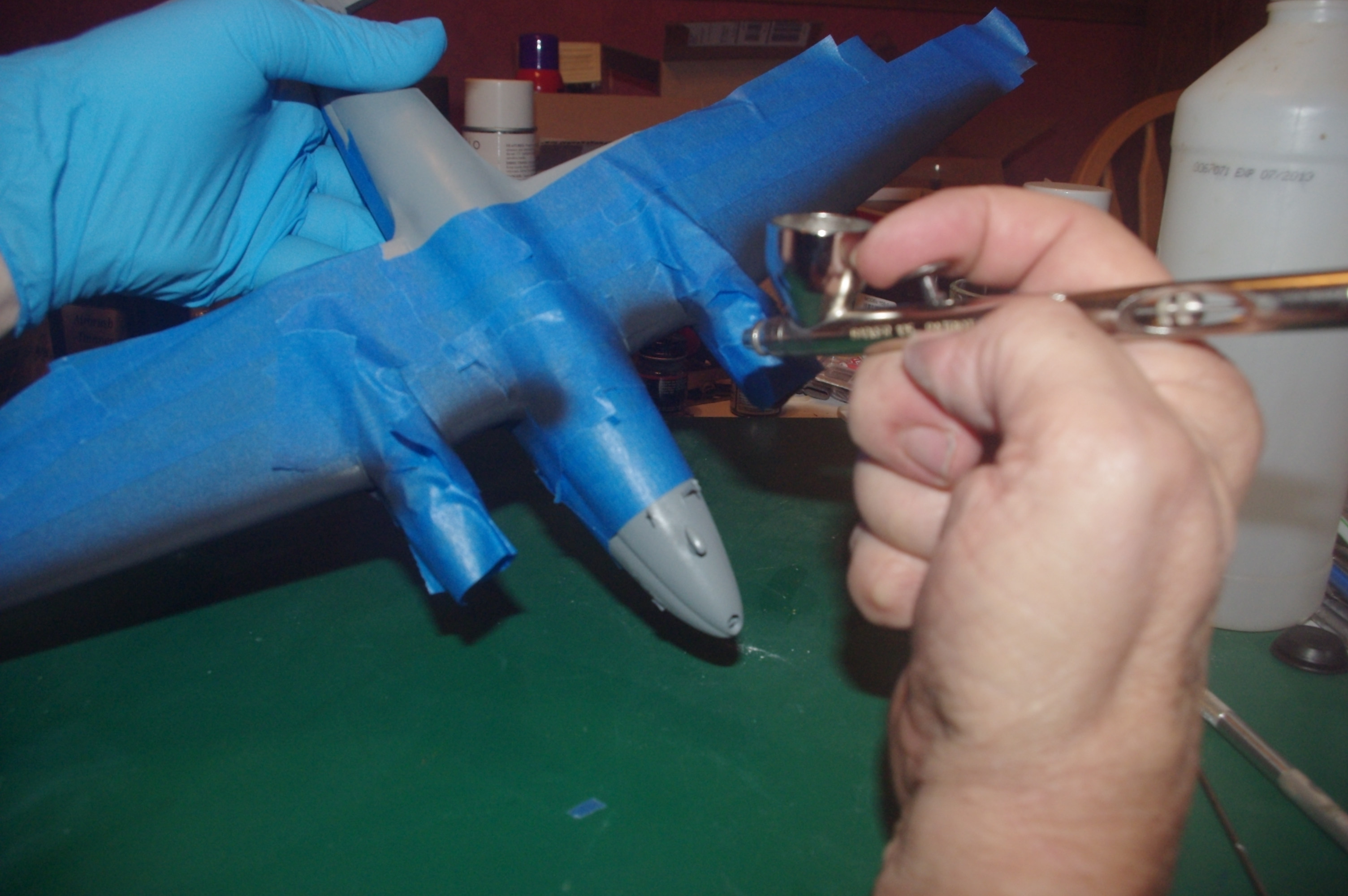
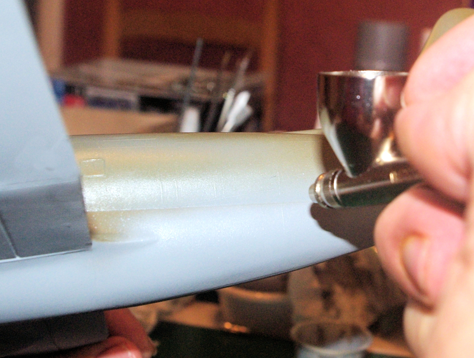
Here's the latest on the C-46: Once the Future has dried, the deice boots were masked off with blue painters tape. Depending on how you like to work, you could mask the boots on the bottom of the wing and then paint'em before... ...tackling the top, leaving the tail surfaces for last. I chose to mask all of the boots at one time and then.... ...spray'em with Model Master FS37038 Flat Black in a single session. By the way, here I'm using a Badger Patriot 105 double action airbrush that I had to buy after losing the needle cap from my Iwata HP-CH airbrush so I could keep working while waiting for a new cap to arrive. With all the tape removed, we have a very nice set of deice boots on the undersurfaces.... ....and on the uppersurfaces. Now to give her some legs to stand on. The tailwheel strut/wheel is a single assembly, so I brush painted the tire first with Pactra M-1 Scale Flat Black or any Scale Black of your choosing. Then the assembly was installed with BSI Super Gold + CA. Don't be surprised if you have to either thin down the mounting shaft or slightly enlarge the mounting hole. The Scale Aircraft Conversions main gear have been completed by the addition of the torque links. When installed, you'll want to make sure that the links point to the rear and the end of the axles to the outside. In this photo, the starboard strut is on the left and the port is on the right. The retraction link in the SAC metal set is where you'll run into trouble. The links are handed, so the mounting recess for the strut connection should be handed as well. Scale Aircraft Conversions has been notified and is checking stock to see how widespread the problem is. If you have one of these problem sets, the solution is easy. Simply drill the mounting recess all the way thru with a .031" (or 1/32") drill bit as I've done in this photo. Note that you only need to do this to two of the links. Here you see the complete SAC starboard main gear properly installed. All it lacks is the wheel/tire and doors And a very tight shot of the same completed assembly. Yet another shot of the same starboard gear from the opposite side. The gear doors laid down on a couple of pieces of tape, just prior to spraying the Model Master FS36270 Neutral Gray. When dry, flip'em over, spray some more Neutral Gray and you're done. All that's left is to install'em. Since you can't stick a toothpick or matchstick thru the axle hole to hold the tire for painting, due to the photoetch outer wheel detail, I used the same approach as the gear doors. Paint was Pactra M-1 Flat Scale Black. Incidentally, that paint hasn't been around for a very long time, but I still happen to have a 35 or 40 year old bottle that's perfectly good. But any Scale Black or Grimy Black paint will produce the same results.
-
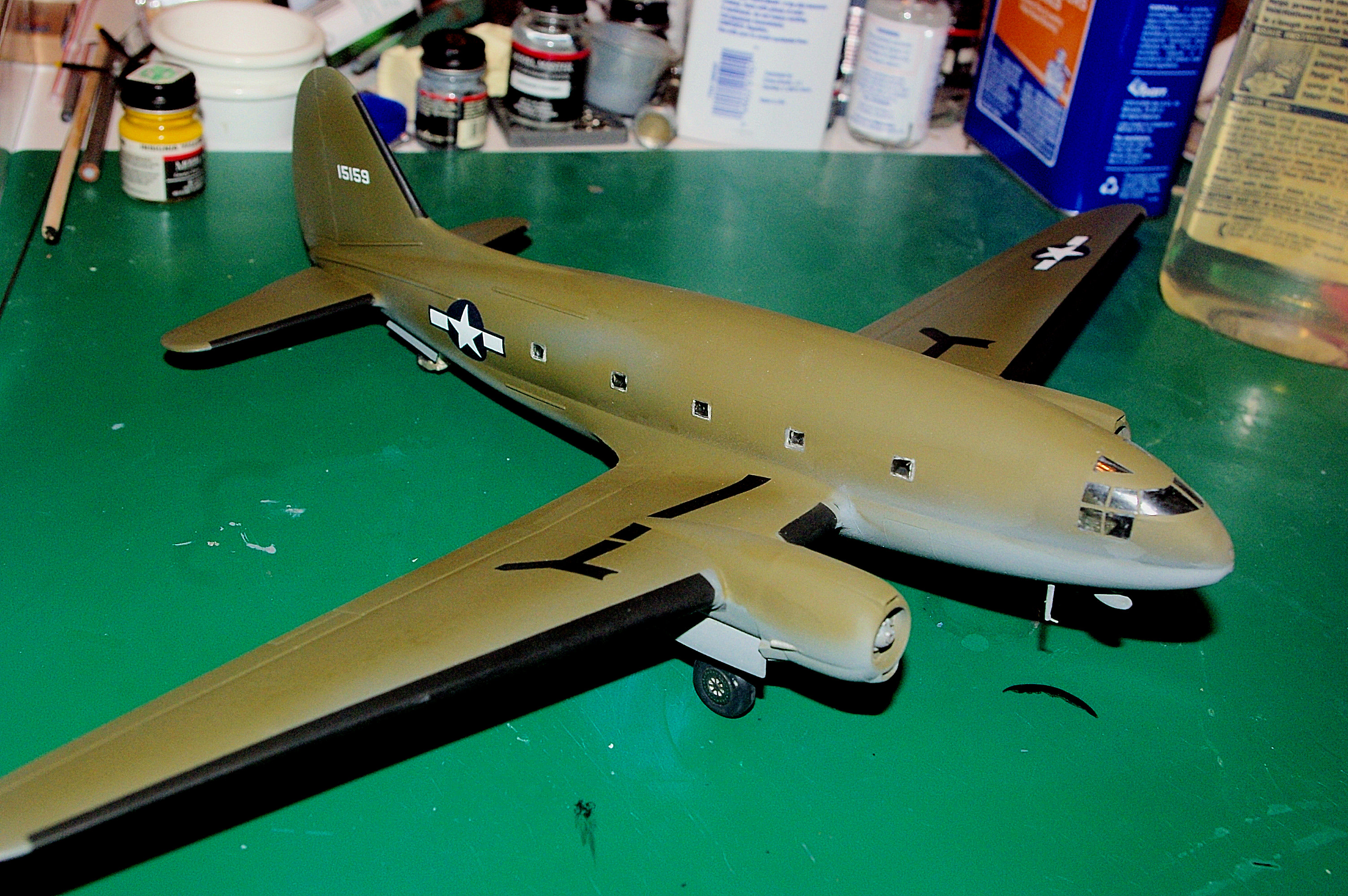
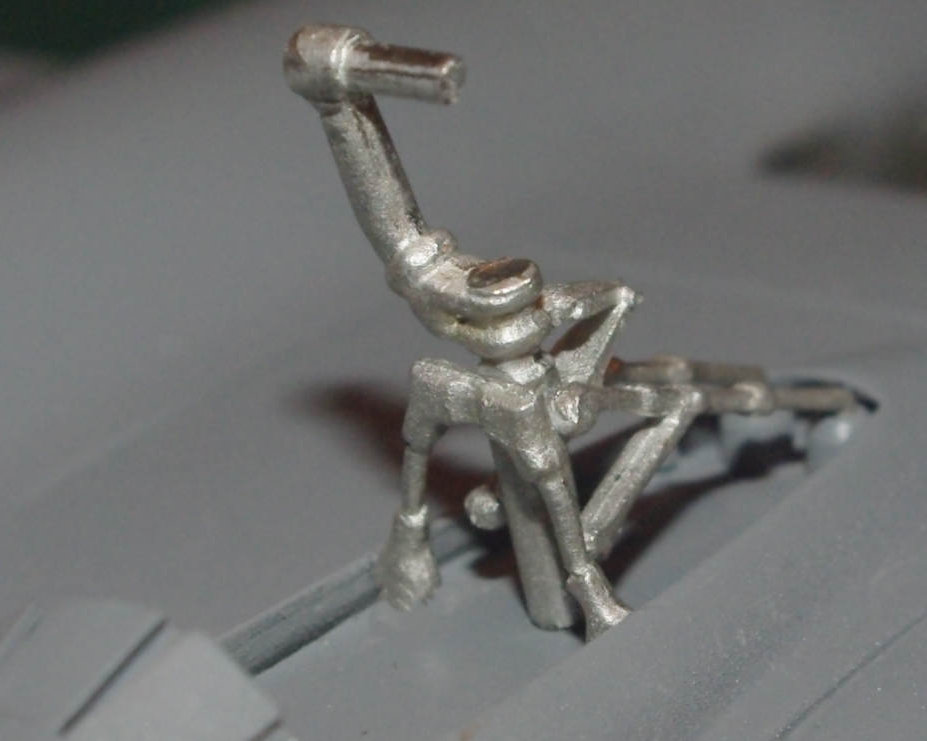
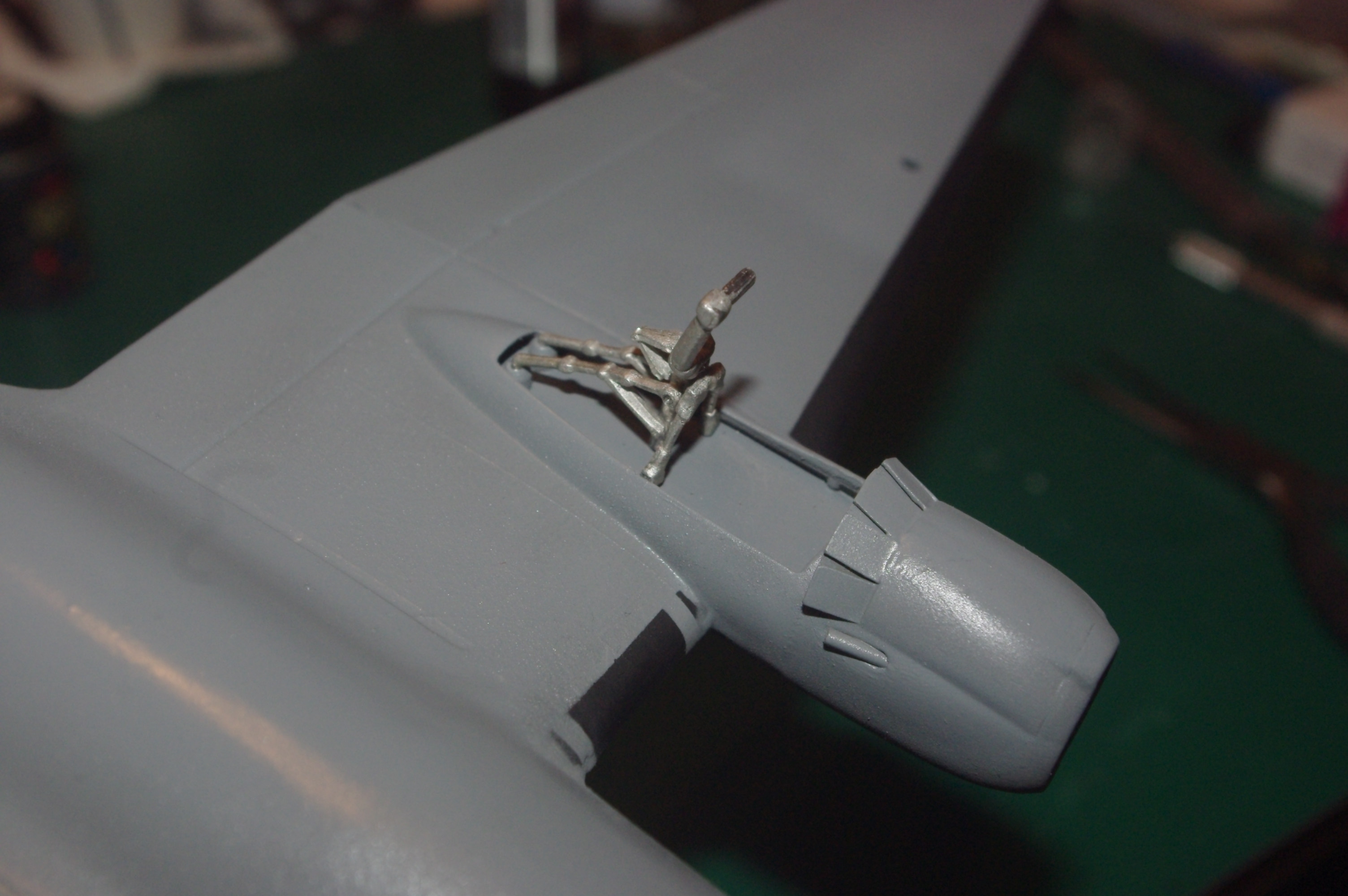
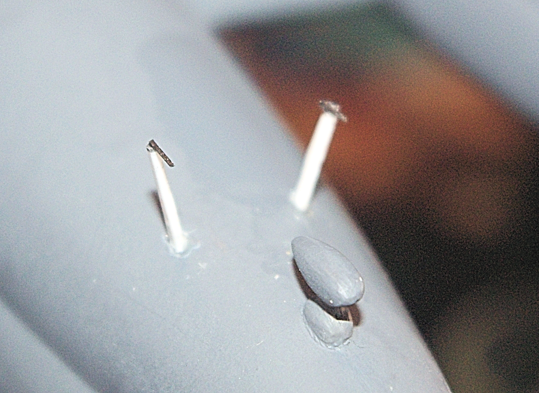
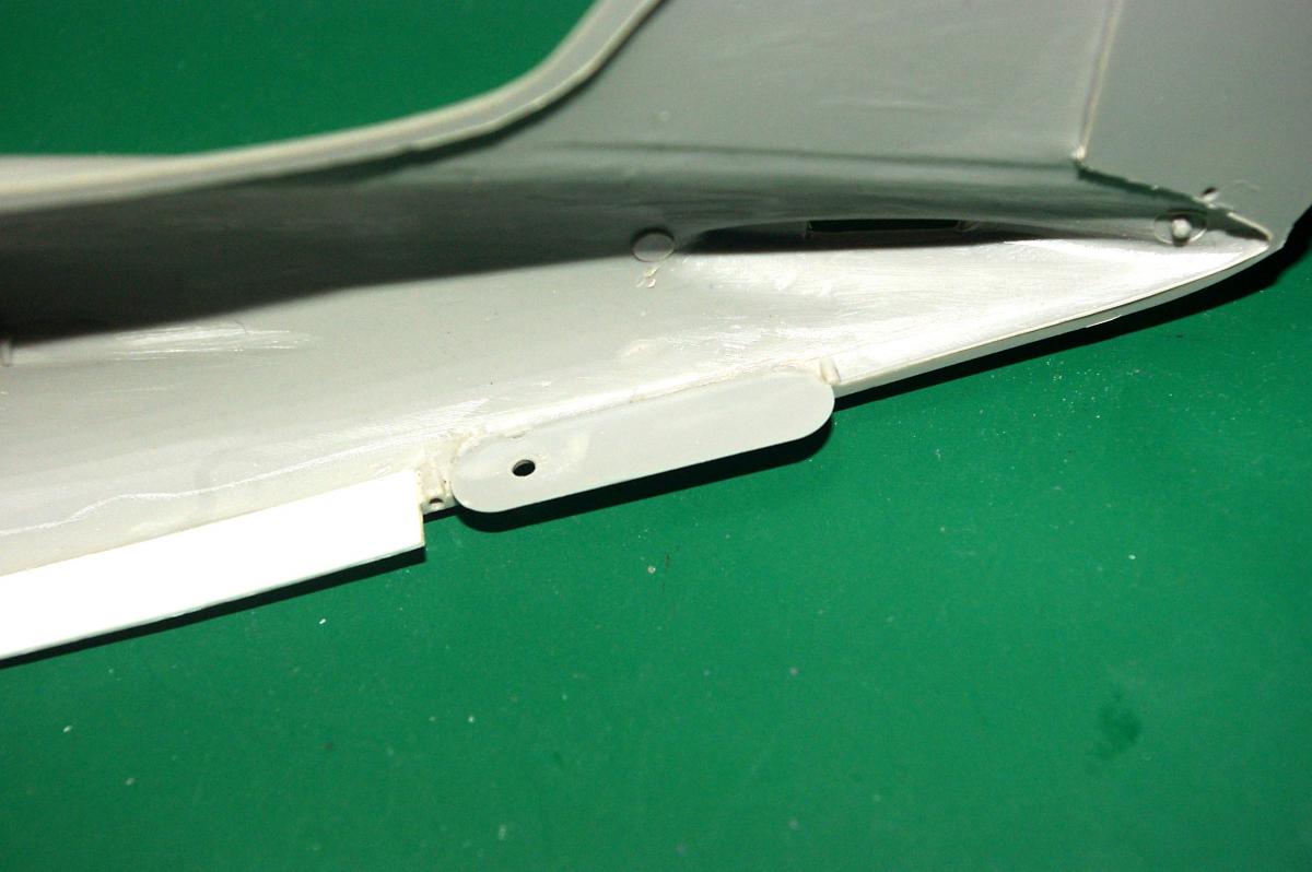
Hi all. Getting close to the end but had to take a breather due to my wife's surgery and an airbrush blowing out on me. Now for this installment: Williams Bros doesn't give you any of the small antennas and masts, which is probably a good thing. This is primarily because of the immense variety that were employed on the C-46. They do provide some reasonably decent patterns on the instruction sheet and tell you to fabricate them from scrap plastic and wire. What they don't tell you is that one of the 'masts' holds a pitot tube at the bottom and you will need two of them. It also doesn't hurt to have experience scratchbuilding minute details and an OptiVisor will be an absolute necessity. This photo shows the two pitot tubes/masts that I built from .030" x .060" Evergreen strip and .016" music wire. The finished pitots/masts are too thin to drill a hole for a mounting pin, so I cut mounting holes in the fuselage. Check you references closely for proper location and keep your eyeball computer nearby. The best I can offer for location is about .40" aft of the rear canopy edge and .90" below the bottom canopy edge. Each mast angles out so that the two form a wide V when viewed from the front. When properly installed, this is how they should look. Incidentally, they are not leaning back. That's the result of the camera angle. You want to be sure that they are perfectly vertical when viewed from the side and form a V when viewed from the front. Almost finished with the basic paint job. Model Master FS34087 O.D. uppersurface and FS36270 Neutral Gray undersurface. With the basic paint job done, a gloss coat of Future (aka PFM) is sprayed prior to decal application. Before the decals go on, I'll also have to install the gear, as well as paint the deice boots and fine details.
-
- 1
-

-
- williams bros
- curtiss
- (and 7 more)
-
Installment #8 of the Williams Bros C-46 build is now online in the Builds sub-forum. Comments are welcome.
-
- 1
-

-
- Williams Bros
- C-46
- (and 5 more)
-
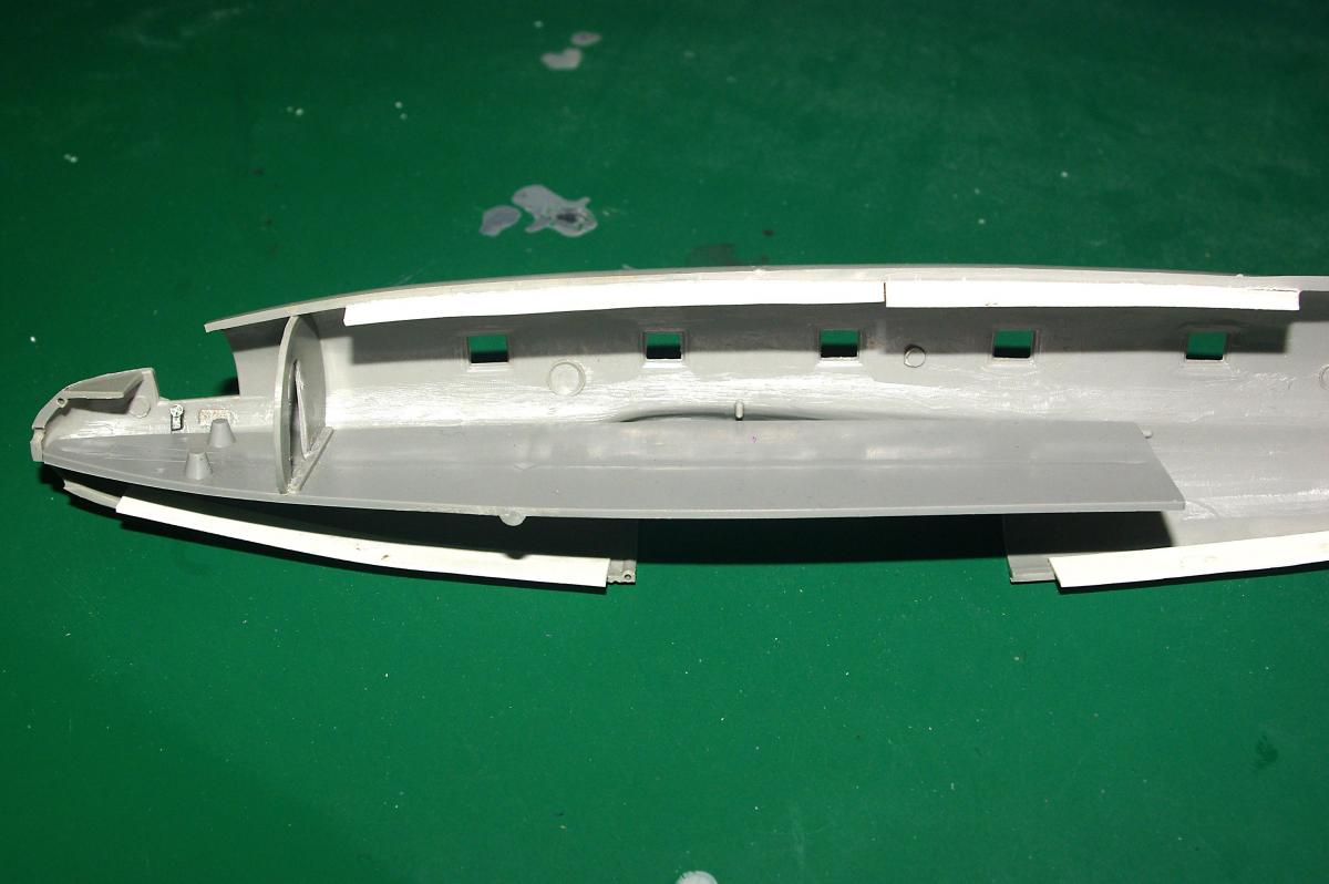
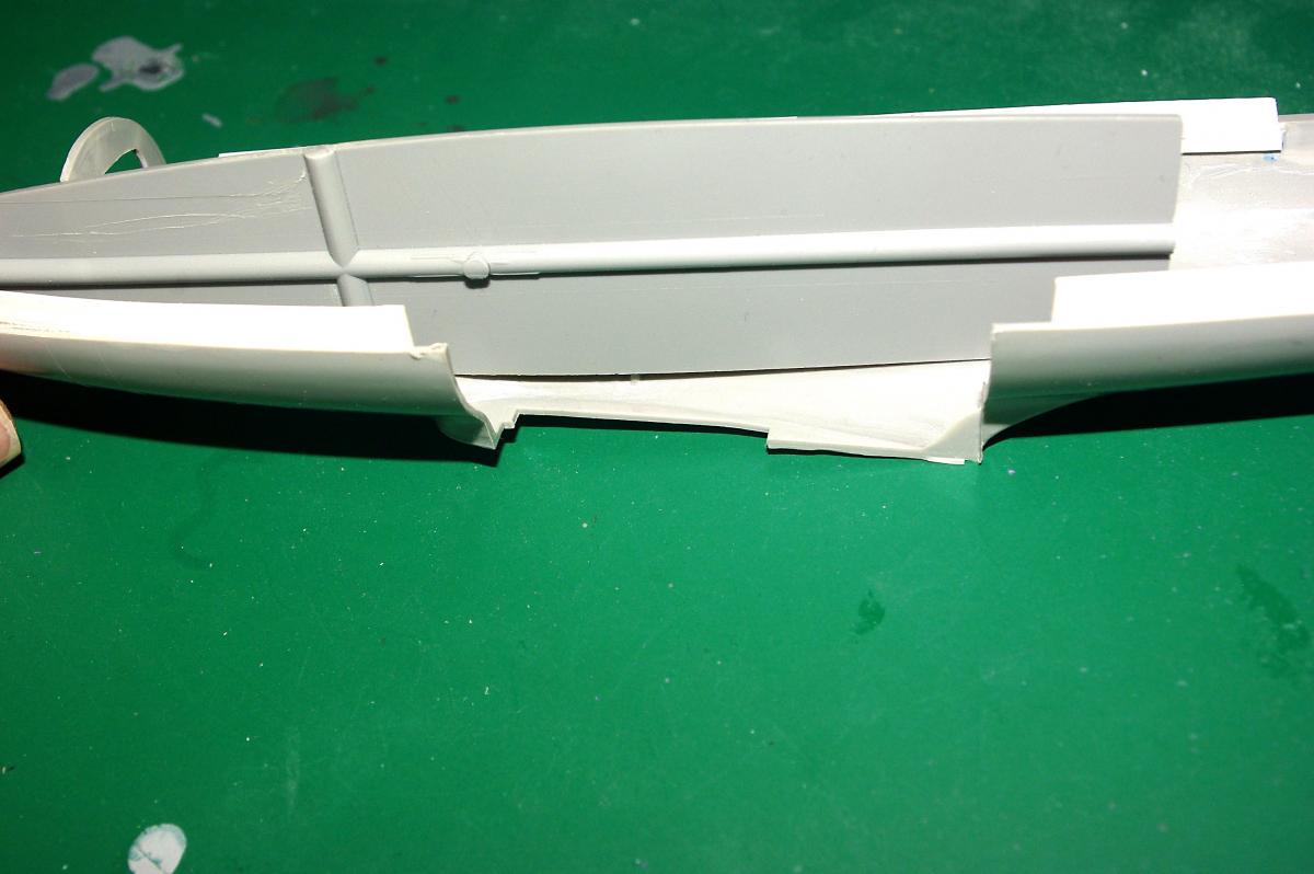
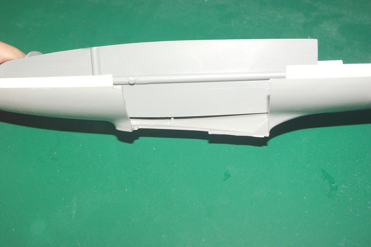
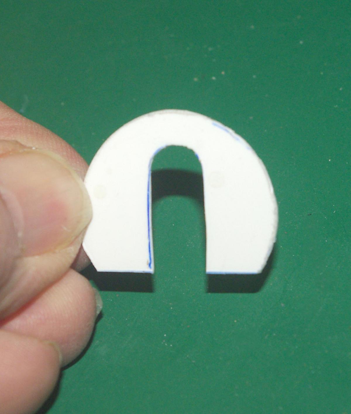
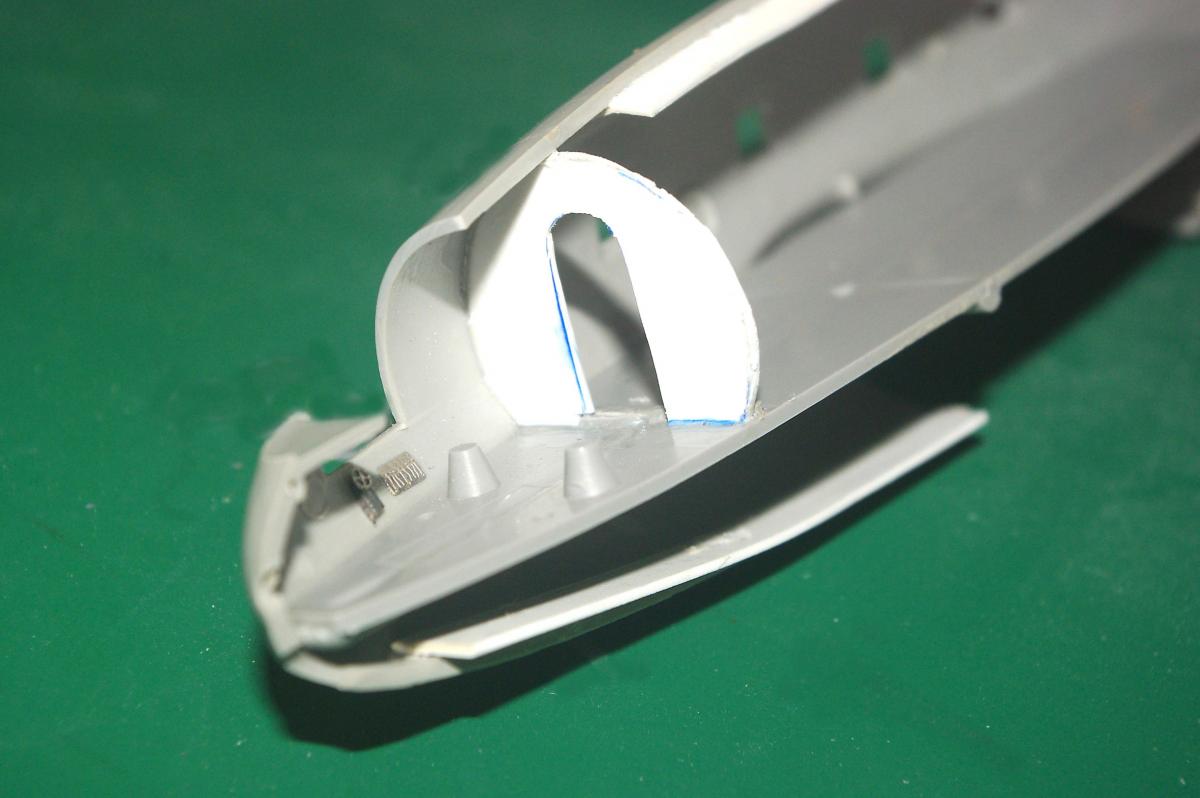
Hi all, Finally back at it. Just like the main gear wells, an insert supports the tail wheel but does nothing to represent the correct gear well appearance. Here the main floor section has been installed. Notice that only the forward third, bulkhead and a small piece of the back actually make contact with the fuselage side. This bottom view shows how much of the floor doesn't touch the fuselage. Another angle shows the substantial gap that will have to be filled if you want to do an interior cutaway. From the top, in order to keep the floor flat, it goes under the center stud and over the after stud. A second floor section will be installed on an incline so that it is level when sitting in a 3-point position for loading freight. Some interior suggest that the forward bulkhead door is located in the center instead of offset behind the pilot's seat. Presumably this occurred on later (civil?) versions, the offset opening being found on the early military birds. Since my client wanted a military version, I built his that way. If you want to center it, first outline the bulkhead on a piece of .020 styrene. Then center the offset opening you'd cut in the original bulkhead and trace it on the new bulkhead. Now cut it out. There you have it. A centered door in a new bulkhead, ready to install. And finally a new centered door bulkhead/floor installed. This shot is for reference only since I will be replacing this bulkhead with my original bulkhead that was modified with an offset door.