


Wolfman63
-
Posts
624 -
Joined
-
Last visited
-
Days Won
109
Content Type
Profiles
Forums
Events
Everything posted by Wolfman63
-
This next build is a commission build using the 1/48 Revell/Monogram AV-8B kit. The client supported the Marine squadron VMA-223 in Afghanistan in 2011. In appreciation of his support they carried an American flag on a mission aboard and aircraft call sign “ALAMO 12”. Upon their return the American flag and a certificate were presented to him. I have been commissioned to replicate the aircraft. The client supplied the kit to use for this build. The build itself will be mostly out of the box with some scratch built add-ons. I will need to add the front sensor pod above the nose, modify the nose, extend the tail scoop, and add the two chaff panels in the top half of the fuselage near the tail. All of the decals will be made custom for this build. Starting off with the cockpit I detail painted the instrument panel and side panels. The seat had only the lower seat belts molded in. I used some cloth tape to make the shoulder straps and upper seat belts. I then looked over the canopy. Harriers have an antenna on the inside of the canopy. Revell molded these on the outside of the canopy giving the canopy a distorted look. I decided to use a decal on the inside for the antenna so I sanded the canopy using 1000 grit then 3600 grit sandpaper to remove the molded antenna and then it was polished with Meguire’s PlastX polish to restore the canopy to a clear glossy finish. The intake was then painted and the cockpit tub installed so the fuselage halves could be assembled. The instrument panel was then installed and I began to work on the tail section for the extended scoop and the chaff panels. There were roughed in with styrene. I am working on the forward sensor and then will blend the add-ons with some putty. You can see all the photos and details from the start in my build log at: https://davidsscalemodels.com/build-log/1-48-av-8b-harrier/
-
Nine weeks and the “Viper” has been completed! All of the panels and canopy doors have been installed. I used 30 gauge wire for the supports on the panels. On the canopy doors I used black sleeved wire and stripped half of it so it look like the compression supports. I did a little more weathering on the inside and outside of the panels. The next thing I did was to remount the weapons. The kit instructions have you mount two rocket launchers and the Hellfire’s under the wing. The problem is the “Z” only has three hard points instead of four. A fellow modeler pointed this out and the client also noted it as well. For the main rotor I trimmed off the plastic links and replaced them with black 28 gauge wire. This allows the rotor to be removed and installed easily. This is for shipping reasons. With the main rotor finished this also finished this build. The kit itself was a decent build with only some minor issues as noted during the build. The fit was very good. The instructions were in a good assembly order but had some parts not shown like the canopy handles. The paint schemes use the incorrect colors as well. It does build into a nice looking helicopter. I will be packing this up today once the brass nameplate arrives and then ship it out. The client already has the display case for it. Thank you for following along. Happy modeling! You can see all the photos and details from start to finish in my build log at: https://davidsscalemodels.com/build-log/1-48-ah-1z-viper/
-
As the eighth week closes on the Viper I finished all the weapons and have them mounted onto the fuselage. The kit does not supply decals for the assorted weapons. I had some spares for the rocket launchers and the Hellfire missiles but no decals for the AIM-9’s so the stripes were had painted. From the last update I received many questions on the paint colors used. The kit painting instructions call out to use FS36270 Neutral grey for top and FS3495 Light Grey for lower part of the fuselage. These colors are not the correct colors for a U.S. Marine AH-1Z. I have a copy of the MIL-STD 2161C which is the official Military standard for painting and markings of U.S. Navy and Marine aircraft. There is a website called “Everyspec” ( http://everyspec.com/MIL-STD/MIL-STD-2000-2999/MIL-STD-2161C_49692/ ) that you can download this document as a PDF. It should also be noted that they have TO 1-1-4 which is the USAF aircraft painting and marking document as well. Anyhow, The MIL-STD calls out FS35237 Medium Grey on the top and FS36375 Light Ghost Grey for the lower part of the fuselage and these are the colors I used on this build. I then started to polish and paint the side panels of the canopy. On the canopy panels that open there is a spot to attach the handles. I looked over the instructions and there is no reference that tells you to install the handles. It should be noted in step 16 or 21. Step 20 does not show the handles installed but step 21 does in the illustration. The parts are included on the tree. They are parts D32 and D33. I used some canopy glue to attach them. I need to review the reference photos for where the supports go on all the open panels and then I can install the panels and then finish mounting the main rotor to finish this build over the next week. You can see more photos and details from the start in my build log at: https://davidsscalemodels.com/build-log/1-48-ah-1z-viper/
-
The seventh week of the Viper I applied all the decals for the scheme. The kit decals are very good. The decals laid down and conformed to the surface with just the decal set. Once the decals had dried I sprayed a light coat of matte clear coat to seal the decals. I then used some light grey and medium grey chalk to add some weathering along the fuselage. I then added the clear lights. One thing the kit did not provide was a clear lens for the tail navigation light. I trimmed off the molded section and replaced it with a clear lens. I then added some photo etch details to the top of the canopy. I checked the fit of the canopy top and it will need some minor sanding on the front underside to meet the fuselage. I then started to assemble the weapons. The 70mm HAP’s, LAU-68’s, and the Hellfire’s went together very well. The AIM-9 missiles had some mold marks that needed to be filled with putty. I also trimmed off the nose to make my own sensor heads using acrylic gel. Once the weapons are completed I will install all the panels and the rest of the canopy. I need to work on mounting the main rotor as it needs to be removable for shipping later. I am hoping to have this completed in a week or two. You can see more photos and details from the start in my build log at: https://davidsscalemodels.com/build-log/1-48-ah-1z-viper/
-
FS - 1/48 Aircraft and two 1/28 aircraft kits
Wolfman63 replied to Wolfman63's topic in Wanted/For Sale (public)
All have been sold. Thanks for looking. -
After six weeks the Viper now has paint on it. Once I added a few more details to the fuselage and mounted the gun turret I painted the base coat of the scheme. I used reference photos from the client rather than the paint guide of the kit. The kit scheme is very close to the actual aircraft. The major difference is the main rotor is half black and half grey and the line between the upper grey and lower grey is slightly different. I ten painted some of the details like the antennas, sensors, and formation lights. One more issue I found on the kit is the Air Data Probe. This sticks up just forward of the cockpit. It consists of three parts, the pole, a junction and a round sensor. The instructions and the reference photos show the junction on the pole shaft. However the kit part does not have a hole in the center to slide onto the pole. I drilled a hole through it using a 0.5mm drill. Once in place the sensor points towards the rear of the aircraft. There is no mounting hole on the backside so using the same drill I made a small mounting hole as well. This coming week I will be applying the numerous decals as well as working on the canopy details. You can see more photos and details from the start in my build log at: https://davidsscalemodels.com/build-log/1-48-ah-1z-viper/
-
I have the following kits for sale: Trumpeter 1/48 Hawker Sea Fury FB.II Parts still in original bags. Price SOLD Monogram 1/48 T-28D Fighter/Bomber - 1965 edition Note that the decals have yellowed a bit but everything else is still on trees. Price SOLD Revell 1/28 Fokker DR.1 WW I Aces edition Parts are not bagged but have verified they are all there. Price SOLD Revell 1/28 Sopwith Camel WW I Aces edition. This even includes the original iron-on transfer. All parts have been verified (not sure if these were bagged originally) this also has two sets of decals. Price SOLD Tamiya 1/48 F4D-1 Skyray The upper and lower fuselages have been removed from the trees. All other parts still on trees. Price SOLD . Revell 1/48 A-1H Skyraider "History Makers Limited Edition" Still factory sealed. Price - SOLD Revell 1/48 A-10 Warthog Parts still in original bags. Price - SOLD Shipping - Free UPS shipping with tracking (U.S. Only) Payment - Chime, Zelle, Postal money order or Stripe. For Stripe I will send an invoice. I do not take Paypal.

-
Five weeks into the “Viper” I added the exhaust to the fuselage. The exhaust was painted using Vallejo Jet Exhaust then heavily weathered with dark grey and black pastel chalk. I next started to assemble the boom and added the photo etch details. The boom and the side wings were then attached to the fuselage. I built up the main and tail rotors then began adding the photo etch to the panels that will be open. There are many screens/vents on the fuselage. Some of these are open holes and some screens fit into a panel. For the ones that fit into panels I painted the panels black and then brush painted the screens with thinned paint so the screen holes do not fill with paint before installing them. This will highlight the appearance of these areas. I painted all the photo etch details with a thin coat as well so when the fuselage is painted the overall coat will be even. I noticed the vent just above the exhaust was incorrect in both angle and shape. The vent has a 90* turn which is incorrect. It is more of a 45* bend to the starboard side. The kit vent was trimmed and re-installed correctly. I will be starting some pre-shading and the base coat painting this upcoming week. You can see more photos and details from the start in my build log at: https://davidsscalemodels.com/build-log/1-48-ah-1z-viper/
-
Finishing the fourth week of the Viper build I began building and detailing the turrets. The TSS turret from the kit was replaced with the resin version from Flying Leatherneck. Speaking of the kit version it is very inaccurate. It has two small round lenses and two large round lenses. The actual turret has one small, one medium and one large lens and they are shaped differently. The resin kit does also have an issue. While they give you a prism sticker for the large lens, the resin turret does not provide the clear lenses for the small and medium lenses. I made these from a sheet of clear acetate. The internal sensor faces were painted chrome using a Molotow chrome paint pen. Turning to the gun turret I replaced the kit with the Model Master kit. The brass barrels are a little longer and have the barrel holders in the correct locations. The kit includes a weight that goes inside the turret so it does not tail drag. I then started to add more details to the fuselage. The landing skids have some photo etch details. They were then mounted. I then built the exhaust section and added the photo etch details. To mount it to the fuselage I had to use a piece of styrene to push the mating edge of the fuselage out a bit to line up with the bottom of the exhaust assembly as the fuselage edges were slightly warped inward. Once the seam was glued I removed the support. I am now working on the side wings and should be starting the boom this week. You can see more photos and details from the start in my build log at: https://davidsscalemodels.com/build-log/1-48-ah-1z-viper/
-
Week three of the Viper build was spent adding numerous photo etch details to the forward fuselage and detailing the avionics and cargo bays. The avionics bay detailing was started with the Eduard photo etch parts. I had to drill some .05mm holes thru the photo etch for the cables. I then used some 30 gauge to represent the numerous cables and routed them like the reference photo. I used a little gloss white pant to represent the ID tags on the cables. I located a small fire extinguisher to duplicate the one in the ref photo as well. The other side of the fuselage is a cargo storage bay. The photo etch set provides a cover with handles and the hinge at the top. I then added the various antenna pods and covers for the fuselage. I started working on the intakes by filling the mold marks. Next up is the gun and TSS turrets for the nose. You can see more photos and details from the start in my build log at: https://davidsscalemodels.com/build-log/1-48-ah-1z-viper/
-
As week two of the AH-1Z finishes I spent most of the week building, painting and detailing the engines. There were a few mold marks that needed to be filled with putty on the engine bay walls. For painting I used the Vallejo Metal Air paint. I used the duraluminum for the bright metal, dark grey metallic, and Jet exhaust for the exhaust. For the added details I used 30 gauge wire for the steel lines and sleeved wires of green and blue for some of the hoses. With the cockpit and engine bays assembled I began assembling the forward part of the fuselage. The fit is very good along the seams with some minor putty where they attached to the trees. The poor fit is the well where the gun turret sits. There are lots of gaps. I was able to get most of the gaps close and then putty the rest. I am working on the photo etch details of the forward fuselage now. There are many screens, and access panels to add. Then I will be detailing the gun turret with brass barrels and then the resin TSS turret will be built and detailed. You can see more photos and details from the start in my build log at: https://davidsscalemodels.com/build-log/1-48-ah-1z-viper/
-
My next build is the 1/48 Kitty Hawk AH-1Z “Viper” attack helicopter. This is the first of a few commission builds I will be doing over the next few months. For this build I will be adding the Eduard interior and exterior photo etch sets, the Model Master M197 (20mm) brass barrels, and the Flying Leathernecks TSS Turret. The scheme will be aircraft 47 from the HMLA-267 Stingers. As typical I started off with the cockpit using the Eduard photo etch detail set. The photo etch replaces the kit decals for seat belts and instrument panels. The side armor panels, seats, and side control panels required some putty to cover the mold marks. Everything went together very well. Next I am starting on the engines. I will be detailing these as at least one of the engine covers will be in the open position. You can see more photos and details in my build log at: https://davidsscalemodels.com/build-log/1-48-ah-1z-viper/
-
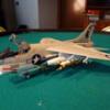
FINAL SCENE: The Lt Jake Grafton’s (Cool Hand) A-6A from the movie “Flight of the Intruder” is finished! I spent the eighth and final week completing the decals. The fuselage was then top coated with clear. I attached the forward nose gear door, the TER’s loaded with MK 83 bombs and the drop tank to the underside. On the topside I installed the windscreen, refueling probe, and canopy. I then painted the back sides of the tail and wingtip lights with chrome. The clear lenses were applied and then painted with Tamiya clear paints. This completed the build. I had a plastic base that looks like a flight deck and decided to place the aircraft on it. I have some custom decals to make for a client and will add a decal that I can add the trim of the base later. As for a review of this kit, it is a mostly decent kit. The biggest issue was the fuselage fit just forward of the cockpit. This required the most work to correct. The rest of the kit had a good fit with minimal putty along the seams. The shape of the top of the tail is also slightly off from the real aircraft. The top is a little flatter on the kit. A few minutes with some sandpaper and the shape was corrected. The instruction sheet is well laid out with a good assembly flow. Even though many of the aircraft scheme decals were made by me I did use the kit decals for the general things. The kit decals are very nice. They went down and adhered to the surface very well. The finished model looks great. The Eduard photo etch sets add nice details. The resin accessories worked out great. I am on the fence about recommending this kit only because of the fuselage fit. Overall I am pleased with the finished product. Thank you for following along on this build. Happy Modeling! You can see all the photos and details from start to finish in my build log at: https://davidsscalemodels.com/build-log/1-48-a-6a-intruder-flight-of-the-intruder/
-
SCENE Seven: Week seven has arrived and I am still having brief time on the bench. However, with the time I was able to sit at the bench I completed the painting and detailing of the canopy and windscreen. I also finished the nose gear door. I really like the Molotow chrome paint pens. I used it on the canopy mirrors and the landing light. The fuselage had some small painting to be done on the formation lights. I also built the centerline drop tank and finished it off with painting and decals. I added the placard decals to the MK-83 bombs as well. Next I started the decaling of the fuselage. I am using a mix of the kit decals for the standard markings and the custom decals I made for the movie scheme. Hoping to finish this build over the next week but we will see how much bench time I can get this week. You can see many more photos and details from the start in my build log at: https://davidsscalemodels.com/build-log/1-48-a-6a-intruder-flight-of-the-intruder/
-
SCENE SIX: The sixth week of the A-6A is now “feet dry”. I am slowly getting more time on the bench. This week I installed all the landing gear and most of the landing gear doors. I am saving the forward nose gear door until after the rest of the aircraft has had its top coat applied. I painted the tail hook and other details on the fuselage like the jet exhaust and CHAFF blocks. I also added the final photo etch details for the fuselage like the antennas and panel details. I installed both boarding ladders as well. The aircraft just needs a couple of items added then it will be ready for the decals. I spent one evening studying many screen shots I pulled from the movie and created the decals I need for the specific scheme of “Devil 505”. Finishing up the weeks work, I added the photo etch details to the windscreen and canopy then hand painted the black insides of the frames. I am starting to mask the outsides so I can apply the base coat and top coat. I am hoping to complete this build within the next two weeks. I also hope everyone has a safe Memorial weekend remembering our military members who never made it back from performing their patriotic duties. You can see many more photos and details from the start in my build log at: https://davidsscalemodels.com/build-log/1-48-a-6a-intruder-flight-of-the-intruder/
-
SCENE FIVE: Five weeks into Intruder and just like in the movie, I am doing the first run “downtown”. It has been a busy week with my career job and with spring here I have been taking care of things around the house so my time on the bench has been limited this week. I was able to get the fuselage masked and sprayed the white areas then turned my attention to painting the other parts. The resin triple ejection racks were painted and then the decals that came with the set were applied. Since the boarding ladders will be in the down position I had to fill the mold marks with putty and then added the photo etch details to the ladders. I also used some 30 gauge red wire for the handle. These were then painted red. Next came all the painting of the landing gear doors. I pre-shaded the edges and will finish these with some post shading prior to installing them. I also painted the edges the safety red. I also painted the splitters on the intakes red. The bombs were all painted as well. Finally, I base coated the rest of the aircraft. As mentioned previously the paint scheme is not accurate to the time period however it matches what they used in the movie. The underside was painted using Light Ghost Grey, the topside was painted with Dark Ghost Grey, and the area between nose and windscreen was painted anti-glare black. I am now working on installing the landing gear and all the other parts as well as preparing for making and adding the custom decals to match the movie scheme. You can see many more photos and details from the start in my build log at: https://davidsscalemodels.com/build-log/1-48-a-6a-intruder-flight-of-the-intruder/
-
SCENE FOUR: For the fourth week of the Intruder was spent mostly working on the nose issue. First I sanded down the fuselage side down a little bit as close as I could to match the nose. I then taped the windscreen with kapton tape as the putty does not adhere to the tape very well. I tacked the windscreen down with some Elmer’s glue to hold it in place and I applied the putty. Once the putty had dried I carefully remove the windscreen and wet sanded the putty down. I had to add a little more putty occasionally to aid in blending the nose to the fuselage. The kit has a small fret of photo etch which included the hinge brace for lifting the nose for access to the radar. This was attached and I then taped off the aircraft nose, flaps and rudder so these could be sprayed with the white base coat. I used one layer of Tamiya white primer then Vallejo matte white for two coats. Once dry I removed the tape and had a slight accident. The tape pulled the ejection seat upper handles. I will re-attach these later after I spray the base coat on the fuselage. While the putty was drying I was able to assemble the Eduard TER’s that will be used. The cables were molded on but they were very fragile and broke easily when attempting to trim the inside of the loop. I decided to remove them and use some wire instead. I adjusted the mounts for these to match the mounting holes on the aircraft. The Eduard set has photo etch details for the bottom of the rack mounts as well. I also built up the Flying Leathernecks resin MK-83 bombs. I also added photo etch details to the landing gear doors and had to fill in some mold marks. I still need to add the panel lines around the nose and some rivet details on the fuselage side after all the putty and sanding. I will be making the boarding ladders in the down position and it looks like these will need some work as well. There are mold marks that need to be filled and then there is a lot of photo etch details that need to be added to the them. I am hoping to get all these little details completed so I can start base coating the fuselage. I have been reviewing the movie multiple times. The paint scheme is kind of weird. Normally the Viet Nam era aircraft were gull grey top and white underside. The movie aircraft was painted light ghost grey with a dark ghost grey around the cockpit and spine. The flaps were only painted white on top. The nose, rudder, rear stabilizers, and topside flaps were all painted white. The only other issue is in the movie they note they are using the 1000lbs bombs and the flight scenes show them with the normal free-fall tails on the aircraft. But the scenes where the bombs drop they are using the MK-82 snake eye tails. I will be using the free fall tails as shown on the loaded aircraft in flight. You can see many more photos and details from the start in my build log at: https://davidsscalemodels.com/build-log/1-48-a-6a-intruder-flight-of-the-intruder/
-
SCENE THREE: The third week of the Intruder was spent getting more details of the fuselage placed. The intakes fit very well. I need to clean up the upper and lower seams which I will take care of when I correct the nose issue. I painted up the landing gear and used a Molowtow chrome paint pen on the struts. One of the details I wanted to improve was the tail vent. I drilled it open and then used some fine files to smooth out and shape the vent correctly. I worked on the exhaust by adding some photo etch details and assembled the lower fuselage sections. Moving onto the wings I cut off the very thick molded kit wind splints and replaced them with the photo etch version. I then completed the tail hook bay details and added photo etch details to the main landing gear bays. I started looking at the horrible fit of the nose section. It looks like the fuselage molding is the cause of the problem. The instrument panel fits the width of the fuselage and the sides and bottom of the fuselage line up very well to the nose cone. The small section between cockpit and nose is very thick and incorrectly sized. The starboard side is twice as thick as the port side but is the correct length. The port side is not long enough. The front edge curves do not line up with the nose and the windscreen size as well. To correct this is going to require a couple of layers of putty and a lot of reshaping so the nose and windscreen will mate correctly and the refueling probe will sit on top correctly. You can see many more photos and details from the start in my build log at: https://davidsscalemodels.com/build-log/1-48-a-6a-intruder-flight-of-the-intruder/
-
SCENE TWO: For the second week of the A6-A I started assembling the other assemblies so I can put the fuselage together. Also the Flying Leathernecks 1000lbs bombs and the Eduard Triple Ejection Racks arrived so I can replicate the specific scene’s ordinance load. The nose gear bay was detailed with the photo etch details. I also added some scratch built details for lines, cables, and other features. I also added some photo etch to the inside of the fuselage area. Moving onto the main gear struts there are many photo etch details that added bolt heads, wiring and lines, tie down points and strut details. The main wheels also have photo etch details for the brakes. After the cockpit was mounted I then added details to the tail hook area using the photo etch details. One of the other things about this kit is the speed brakes. The kit comes with the vented panels. The movie aircraft has the solid panels. Typically most A-6 kits give you both the panels but this kit does not so I filled in the holes with putty and mounted them in the closed position. The fuselage halves were then assembled together. The fit was good on the tail and the main part of the upper fuselage. However, the lower area under the wings will need some putty to even out the seam. I also will need to work on the area in front of the cockpit. This is a noted issue with this specific kit. There is a forward bulkhead that mounts in the fuselage. Comparing this to the nose cone everything lines up. Once the bulkhead is mounted to the fuselage there is a 0.1” gap just forward of the cockpit. It appears this is more of a design flaw as the rest of the fuselage to the front bulkhead lines up very well but the gap is still there. The area is very small as there is a cut-out for mounting the refueling probe. I dry fit the nose and it lines up very well with the exception of the gap and the curved areas. It looks like I can reshape the curved areas to match the nose cone and then I take care of the gap. I am now working on taking care of the fuselage issues then moving onto the main wings. You can see many more photos and details from the start in my build log at: https://davidsscalemodels.com/build-log/1-48-a-6a-intruder-flight-of-the-intruder/
-
Last year I built a 1/48 R4D-5 that was featured in a movie called “The Thing from another world”. I had so much fun building the aircraft to match the movie that I am doing another movie aircraft. I am using the Hobby Boss 1/48 scale A-6A Intruder and will be making it the aircraft used in the 1991 movie “Flight of the Intruder”. For those unfamiliar with the movie, it is about a Navy pilot Lt Jake Grafton (Brad Johnson) and his bombardier LCDR Virgil Cole (Willem Dafoe) who flies an unauthorized mission to bomb the “SAM City” during the Viet Nam war in 1972. The aircraft will be built to replicate the aircraft as depicted on that particular mission from the movie. I will be using Eduard’s “Big Edition” photo etch set as well as Eduard resin racks and Flying Leathernecks resin bombs to add details. I will be making custom decals for the aircraft for the specific names and numbers on the aircraft. The scheme of the aircraft is that of the A-6 squadron VA-196. Since the movie is a fictitious event the actual ship used in the filming of the movie is the USS Independence (CV-62) and they kept it the same ship for the movie so I will use that for scheme. For those familiar with VA-196 will note that in 1972 the squadron actually operated aboard the USS Enterprise. The actual Navy squadron used was VA-165 and had four aircraft painted as VA-196 for 1989 filming of the movie. Beginning with “scene 1”, I started by detailing and assembling the cockpit. The ejection seats were assembled and detailed with the Eduard photo etch. This set includes all the seat belts, levers, and placards for the seats. Once the seats were finished I then moved onto the cockpit tub. The photo etch includes side panel details, pedals and all the controls for the side panels and center console. On the instrument panel shroud I cut out the molded vent and added the photo etch version. Details were then added to the deck behind the ejection seats. Aside from the photo etch details I added some wire to replicate the cables for some of the avionics on the deck. The kit instrument panel was sanded down to remove the molded details and then the photo etch sections were installed. The instrument panel was then installed into the shroud. The deck, ejection seats, and instrument panel were installed on the tub completing the cockpit assembly. I am now working on the nose landing gear bay, landing gear, intakes, and the tail hook section so the fuselage can be assembled. You can see many more photos and details in my build log at: https://davidsscalemodels.com/build-log/1-48-a-6a-intruder-flight-of-the-intruder/
-
The Burma Banshees P-40N is now finished. For this final week I applied all the decals. The “Lulu Belle” being two parts was not too bad to get them lined up. The skulls required some finesse to place. If you plan on building this kit I would recommend placing the skulls on before the exhaust pipes. It took a while for me to place the decals in between the exhaust pipes and not damage the decals. The rest of the decals went down very well and conformed to the surface details with a little help from the decal solvent. The aircraft was then top coated with matte finish. I installed the clear parts and painted the wing lights with Tamiya clear paints. The canopy and windscreen were installed and this completed the aircraft. This kit was a nice build. The fit was not too bad with the wing roots being the area needing the most work. The instructions were laid out well and the kit decals were good. The Eduard detail set was easy to install and adds nice details to the cockpit and main landing gear bays. I would recommend this kit as the finished aircraft looks nice and represents 2nd LT Adair’s aircraft very well. Thank for following along. Happy Modeling! You can see all the photos and details from start to finish in my build log at: https://davidsscalemodels.com/build-log/1-48-p-40n-burma-banshees-lulu-belle/
-
The second week of the Lulu Belle covers the detailing of the fuselage and the start of the painting. Using the photo etch detail set I added the mounts for the drop tank and the cowl flaps. I opted to use the open set so the details inside can be seen. The tail wheel doors were replaced with the photo etch replacements as well. The main gear struts were also detailed. I used wire to add the hydraulic hoses to the main gear struts. On the nose there are two vented panels. The kit had tiny marks to represent these but the marks appeared way too small so I opted to use a 0.5mm drill and open the holes up for a better appearance. The underside of the aircraft and drop tank was then base coat painted with neutral gray. While the underside was drying I masked and painted the canopy sections with the olive drab. The topside of the aircraft was then base coat painted with the olive drab. The Banshees scheme had some deep green scallops along the wing edges and tail so I painted them to match the reference photos. I then painted the propellers, nose cone, and exhaust pipes. I added some exhaust staining with some brown, gray and black pastel chalk. I am preparing to start the decals. One thing I noticed was the “Lulu Belle” decals are set up as two parts. Once white then a yellow decal will need to be aligned on top. I will let you know how it goes. I should be able to complete the model by next week. You can see more photos and details in my build log at: https://davidsscalemodels.com/build-log/1-48-p-40n-burma-banshees-lulu-belle/
-
Welcome to my next build. I am getting back into building aircraft and starting with a World War II aircraft. This build is the Academy 1/48 P-40N. I will also be using Eduard’s photo etch set to add details. I will be using the kit decals for the Burma Banshees scheme. This scheme represents 2nd LT. Philip Adair’s P-40N named “Lulu Belle” of the 89th fighter squadron in the 80th fighter group. During his service with the Burma Banshees he actually fly two aircraft named Lulu Belle. The first aircraft was severely damaged in December 1943 when the air base was attacked. 2nd LT Adair after just returning from a mission hopped back into his aircraft and chased the bombers and their escorts. Even though his aircraft was damaged he returned to his base and assigned a second aircraft which he also named Lulu Belle. This will look like the aircraft during the 1944 battle of Imphal-Kohima in India. Starting with the cockpit I assembled the photo etch instrument panel which replaces the kit panel and then detailed the side walls using photo etch accessories. Next I drilled out the lower intake ducts and replaced them with photo etch screens and vanes. The pilot seat was replaced with the photo etch version. This was installed into the cockpit and the seat belts were added. The entire cockpit was installed into the fuselage and the fuselage was put together. The fuselage fit was very good only requiring some minor spot putty. Using the photo etch parts the landing gear bays were replaced and detailed into the lower wing assembly. Once painted and installed the upper wings were installed. I used a 0.5mm micro drill bit and drilled the barrels of the guns. The wing roots mostly fit but required some putty along the seams. While the putty was curing I assembled and detailed the main gear wheels with photo etch. So far this build is going smoothly. Once I have the aircraft cleaned up from the areas that were puttied. I will assemble the landing gear and doors then I can begin the base coat of the paint. You can see more photos and details in my build log at: https://davidsscalemodels.com/build-log/1-48-p-40n-burma-banshees-lulu-belle/
-
This past week the Jupiter 2 was fully assembled and completed! With all the electronics mounted I assembled the interior walls and details. This went together very well and quicker than I estimated. Installing the ceiling was a little tricky as the instructions recommend not gluing the support walls until the ceiling is in place. This was actually a nice note in the instructions. It did take some adjustments to get the walls lined up and into the ceiling slots. Once the ceiling was set I then glued all the supporting wall attachment points. I then installed all the ceiling and wall LED’s and then tucked the wires down. I cleaned up the hull, primed it, and painted the silver exterior. For the battery case I used some sheet styrene and made a case. I added some photo etch handles and a hoist ring on the top. The box was painted aluminum and then I made decals calling it the “Fusion Core Emergency Recharge Unit” with some radiation and two man lift warning signs. I completed the hull by adding the windshield and the radar bubble on top. The client wants the ship sealed so I began the process of gluing the upper hull to the lower hull. Due to size, a slight warp in both halves, and a tight fit due to all the wiring this was a very tedious process. I had to slowly glue the halves at about 2” at a time. Due to the contour of the hull I could not use clamps so I held the halves together, glued the seam, I then held the section until the glue cured. A little final clean up on the seams and the Jupiter 2 was finished. I hooked up the power for the lights and the battery box for the sound board and performed a final check of the lights and sound. Check out the video of the final operation of the electronic features in the build log link below! This project was an interesting change from doing military aircraft. Moebius did a decent job with the kit instructions. They even have little helpful notes to aid in assembly. The only thing I would change on the instructions would be to organize the painting instructions better. Some of the minor assemblies painting notes are scattered within the assembly instructions. Some of the parts required some clean up due to mold marks. The kit decals had two issues. The green radar screens were smaller than the area where they go and the astro-contol station gauge ring decal was thick and cracked easily. Since the assembly fits inside a clear dome the thicker decal was hard to get in correctly. I ended up making my own which made it a lot easier to assemble. The Moebius light kit was ok. I changed the landing bays lighting and made mounts for some of the LED’s as the instructions wants to mount them by their wires and “floating” the LED into position. For the accessories, The Tenacontrols remote control board works very well and is easy to wire up with the enclosed instructions. The Starling sound board works well. It would be nice if they could add a power supply input so that you can use a different source beside the batteries. Using a different power source changes the input impedance which changes the timing of the sound causing the cycle to reset way too early. The resin figures of the Robison family were excellent. Clean up was easy and the figure details were great. I did not use the extra decals. The colors used on the decals seemed off and the resolution of the print was too low for what I prefer. Many of the panels looked much better painting them. Overall it was an interesting build and not as complicated as I first thought. I hope you all have enjoyed this project. Thank you for following along. Happy modeling! You can see all photos and details from start to finish in my build log at: https://davidsscalemodels.com/build-log/1-35-jupiter-2-lost-in-space/
-
This is the 5.5 week of the Jupiter 2. After ten days of an unscheduled break for a minor medical issue I am finally able to get back to the bench! The “.5” (half week) notation is because I have only had a couple of days of work on it. I started with installing the deck LED’s. I am using the acrylic gel medium to hold them in place. For the freezing tubes the instructions tell you to glue the wires down with the LED bent upwards. I did not like how they just hang there so I used some thin styrene sheets and mounted the LED’s to them then attached to the bottom side of the deck. With the LED’s mounted I then checked out the sound card. The sound out of the speaker is a little muffled and since the saucer will be sealed I decided to make a speaker grill. Instead of drilling holes like I have seen on other builds I decided to cut slits on the cargo doors. The doors have ribs already so I just sawed them open. Once cleaned and repainted they will be very hard to see but allow the sound to project out. Next I purchased a small dual relay board. These relays will be controlled by the remote control board to turn on the light kit and turn on the sound card from the remote. I mounted the speaker by using two styrene square rods then mounted the relay board in front of it. I then removed the batter board from the sound card and ran the power to a mono jack. The battery pack was then mounted to a mono plug. This will allow the battery pack top remain out of the ship and allow batteries to be changed in the future. I plan on making a battery box to look like a storage container that may have been used aboard the ship. Next I need to sort out which LED’s go to which walls and then mount the LED boards to the bottom. I can then start installing the previously completed interior pieces. You can see more photos and details from the start in my build log at: https://davidsscalemodels.com/build-log/1-35-jupiter-2-lost-in-space/


