Wolfman63
-
Posts
624 -
Joined
-
Last visited
-
Days Won
109
Content Type
Profiles
Forums
Events
Everything posted by Wolfman63
-
Week three of the YF-23 I finished up the cockpit. The panel behind the seat was detailed and mounted and then I worked on the instrument panel. At first glance the instrument panel decal supplied by the kit looked to be a little too large for the instrument panel. The instrument panel itself was actually detailed very close to the PAV 2. I decided to paint the panel and all the details. For the instrument screens I scanned the decals and then resized the screen decals to fit in place. The instrument panel was installed and I dry fit the cockpit into the upper fuselage. This completed the cockpit. Under the cockpit is the nose gear bay. The details were very close to the actual bay so this was just detailed painted. The main gear bays have good details as well. However there are numerous lines throughout the bays. I will be using some tin solder to replicate these. One thing to note is the actual main bays are not painted as they would be on a production aircraft. I detailed painted the port bay to match the reference photos. I am working on adding the numerous lines in the port bay and then onto the starboard bay. There is still the intake and exhaust to be added then I need to start doing the modifications to the fuselage. There are numerous vents that need to be opened up and one vent that needs to be added just behind the canopy. I did order some photo etch screening for the vents. You can see all the photos and detail of this start in the build log at: https://davidsscalemodels.com/build-log/1-48-yf-23-atf-black-widow-ii/
-
Yes I make the decals myself.
-
For the second week of the YF-23 I am still working on the aft section of the cockpit tub. I finished up the cable assemblies on the rear bulkhead and then I installed the ejection seat so I could measure the size I needed for the panel. The panel was made from a piece of sheet styrene and then covered with photo etch sections. A support bar was added to match the reference photo. I am not sure what the green/blue mount is but I replicated it with more photo etch. I then built the canister assembly out of styrene rod and used a photo etch screen for the base. Next I used a photo etch frame to make the mount for the canopy rod. The panel was then mounted into place. I added the custom decals for the ID plate and the duct warning placard. In the reference photo there appears to be aluminum tape around the edge of the panel seams. I replicated this using aluminum paint. I then used some photo etch to make the in-flight camera mount on the ejection seat rail. One of the comments I received was with respect to the landing gear. I was told that the nose gear was very delicate and breaks easily. To solve this I ordered the Scale Aircraft Conversions metal landing gear set. These actually look a little better than the kits plastic version in details as well. I still have one more item to make that mounts on the aft bulkhead and its cable. For custom decals I need to apply the corrected “EXPERIMENTAL” decals and the ID nameplate for the top of the canister to finish off the aft section of the cockpit tub. Then I can move onto the instrument panel detailing and begin detailing the nose gear bay. You can see all the photos and detail of this start in the build log at: https://davidsscalemodels.com/build-log/1-48-yf-23-atf-black-widow-ii/
-
This build is the 1/48 Hobby Boss YF-23. This is a prototype aircraft designed by Northrop was in competition against Lockheed’s F-22 back in 1990. It was nicknamed “Black Widow II” with reference to Northrop’s famous P-61 from WWII. For this build I will be adding Aires resin seat and Caracal’s YF-23 Prototype decal set. I will be building this as the PAV-2 prototype. As a reference I will be using Air Force Legends number 220 book written by Paul Metz. This book is filled with a lot of information on the design and development of the YF-23 as well as many detailed photos of the prototype aircraft. The kit has some items that need to be changed. The first thing is the aft section of the cockpit. This area is more of a “what if” rather than what the prototype looked like. The second thing is the kit does not have the option of having the canopy in the open position. I will need to modify the canopy for these details as well. So to start off I cut out the areas of the cockpit tub that need to be changed. I used a lot of scrap photo etch to rebuild the areas. One thing to note is that the prototypes left a lot of these areas with the zinc chromate coating with no top coat of the grey or black that a production aircraft may have. I added the large white pipe air pipe and started making all the wire cables that mount on the rear bulkhead. I also started making the actuator that raises and lowers the canopy. The ACES II ejection seat in the YF-23 was more like the F-117 version rather than the typical version used other aircraft like the F-16. The main difference is instead of having the ejection handle on the front of the seat between the pilots legs there are two handles on the sides of the seat. I am still working on adding details for the rear of the cockpit tub then I will be moving onto the panel just behind the seat. You can see all the photos and detail of this start in the build log at: https://davidsscalemodels.com/build-log/1-48-yf-23-atf-black-widow-ii/
-
After thirteen weeks the CH-46D helicopter of HMM-165 is finished! I finished off the battery area and dressed the wiring. I was going to make a plaque with the Marine logo and the squadron logo but it did not present well. I decided to add some 55 gallon drums to hide the switch. They were painted and weathered then lined up in front of the switch. The etched brushed aluminum name plate from EnM Engraving arrived and was mounted on the front. For the machine guns I located some better reference photos. I removed the gun sights and added an ammunition box to each. I installed the rotors and the machine guns to complete the project. As for a review of the kit, this was a very good kit to build. The fit was very good. Aside from some of the incorrect details in the crew area the rest of it was good. The instructions were laid out well even though my assembly was different due to the addition of the lighting. The kit decals were very detailed and laid down well. I used 16 LED’s and 6″ of fiber optic lines for all the illumination. Although this project took a little longer than I planned due to the wiring and assembly I am very happy with the final display. I will be displaying this at the 2024 IPMS convention in Madison Wisconsin. Thank you for following this interesting and detailed project. Happy Modeling! Be sure to check out the video at https://videopress.com/v/5e9op3AL You can see all the photos, details, and a video of this build from the start to finish in the build log at: https://davidsscalemodels.com/build-log/1-48-ch-46a-d-helicopter/
-
Week twelve on the CH-46A/D was spent making the display base. I started with 16X12 wooden plaque that I purchased at a local arts and crafts store. I then cut a sheet of .1” styrene for the tarmac. I scribed the tarmac with seams and then sprayed four different grey shades. I measured out the placement of the model and drilled the holes for the wires to pass thru the base. Moving to the wood base I marked the area under the rear part of the model and then cut out a section. This is where the battery and wires will be housed. I also drilled out a hole for mounting a switch to turn on the lights. A channel was made on the topside of the wood base to route the wires from the switch to the battery area. I then used some styrene sheets to make a holder for the battery. The styrene tarmac was then attached using clear epoxy to hold it down to the base. The model was then installed on the base. I hooked all the wires together and performed a quick check to make sure all the lights and switch work. I then added some dirt, stains, and weathering on the tarmac using pastel chalk. I still need to dress the wiring inside the battery area and then add the rotors and guns to the helicopter. The etched nameplate will be arriving early this coming week. I am also going to make a squadron logo sign which will conceal the switch. Stay tuned as this project will get completed over the next week. You can see more photos and details of this build from the start in the build log at: https://davidsscalemodels.com/build-log/1-48-ch-46a-d-helicopter/
-
After eleven weeks on the CH-46 the helicopter is almost finished! I started off applying the decals. The kit decals worked very well. The tedious part was the 60+ placards/stencils. It took three nights to get all the decals applied. These were then sealed with a clear coat. I began removing the kapton tape masking on all the windows and the Micromask from the navigation lights. The navigation light lenses were then painted with Tamiya clear for the color of the light. I then did a quick light check before moving on to installing the boarding ladder and the cargo ramp. On the boarding ladder I used 38 gauge wire for the support cables. The angle of the steps should look better once the helicopter is on the display base. It sits about 0.1 inches higher in the back due to the wires out the bottom of the tires. I did another light check and all is good. I have some minor touch ups to do and then I need to use some compressed air to clear some dust on the inside of the cockpit and I can then start weathering the fuselage. I will be starting the display base next week as well. The plan is to complete this over the next two weeks. You can see more photos and details of this build from the start in the build log at: https://davidsscalemodels.com/build-log/1-48-ch-46a-d-helicopter/
-
Tenth week of the CH-46D was spent adding external details and starting base coat of painting. I built up the lower section and routed the wires (one for each side). The end caps for the landing gear were then modified for the wires. I used the 30 gauge wire to represent the hydraulic lines. These go into the wheel hub and exit thru the middle of the tire. They will later feed thru the base to the power source for the lights. Next I started to add the small external details. One thing I noticed is the kit does not cover the section between the rear door and the crew section. This left the underside of the tail and wiring exposed. I located a reference photo that showed this area covered with the same blanket panels that are above the crew seats. So I used the 3M glass tape on a small frame to fit the area. I then modified the rear landing gear pods and the nose strut to add the tie-down loops. The underside has a couple of antenna’s which are supplied in the kit, however these kit pieces are very thick. The nose small blade antenna was replaced with a photo etch version. The posts for the wire antenna were replaced with gold pins from a scrap computer circuit card. The large blade antenna is the kit part but the thickness was thinned down with sanding sticks. Also on the tail is a small vent tube. The kit piece was plastic with a small hole in it. I replaced this with an aluminum tube. Finally I started the base coat of painting. The overall green is FS34097 with flat black for the exhaust area. This upcoming week I hope to finish up the base coat, final assembly, and start on the decals. You can see more photos and details of this build from the start in the build log at: https://davidsscalemodels.com/build-log/1-48-ch-46a-d-helicopter/
-
The ninth week is my “challenge week” on the CH-46A/D! I call it challenge week because trying to put the fuselage together with all the wiring routed requires all the subassemblies to be put together at the same time. To start with I scratch built the fire extinguishers for the cabin using styrene rods and some solder. Two of these were mounted near each of the gun mounts. The third one will mount near the rear door later. I then began routing the wiring. Starting with the tail the wiring was routed thru the upper panels into the forward bulk head with the other wiring. I used acrylic gel to hold down the wires so they would not interfere with the forward rotor shaft. They were then routed over the bulk head and between the bulk heads between cockpit and cabin. All of this wiring was routed thru the floor and tied in with the wiring for the instrument panel and lower flashing navigation light. The nose light wiring was then run under the cockpit floor and all of the wires were tied together where the rear landing gear assembly will be mounted. I then performed a light check to make sure all the lights were wired in. The starboard side wires were also routed the same way. I then performed a light check to make sure all the lights were wired in. The fuselage halves were then carefully aligned and were glued together in sections making sure not to pinch any wires. With the halves glued together I used some long tweezers to mount the starboard side seats and the upper panels. The wiring was all dressed up and a second light check was done. The lighting effects are exactly how I wanted them to look. I need to clean up the fuselage seams and then assemble and install the rear landing gear assembly. The wiring will be routed thru each of the rear landing gear and tires so they can pass thru the base. There are still a few more details to add the fuselage as well and then I can start with the base coat of paint. You can see more photos and details of this build from the start in the build log at: https://davidsscalemodels.com/build-log/1-48-ch-46a-d-helicopter/
-
Eight weeks into the CH-46D and I am still working on the interior details. The guns are due in this week. While waiting for delivery I started modifying the tail. I opened up the vent on the port side and added a photo etch screen. The inside was then painted flat black to block and light from showing thru. The opto-couplers were mounted to the bottom and I used 0.75mm fiber optics to run to the light points. For the navigation light I melted the tip of the fiber optic to replicate the navigation light. The upper flashing lights will go to the lenses supplied in the kit later after the fuselage is painted. Next I made the twin lights in the nose using two pico sized bright white LED’s. I used kapton tape to mask the nose and the cockpit doors so these can be painted later as well. The guns and ammo belts arrived! The resin guns look way better and their size is more accurate for the scale. I used some scrap photo etch to make the axial mount for the guns. The rear gun sights looked a little thick so I replaced these with photo etch versions. The gun mounts were then cleaned up and painted. I found a few more reference photos that detailed the area around the gun mounts. One thing I noticed was there are a few fire extinguishers near them. I am going to scratch build these. The kit instructions have a very good detail photo of this and the kit section was really bad. The stairs are very thick and the rail was a thick wall. I tried to clean this up and modify it but there was just way too much to modify. I decided to scratch build it from photo etch and styrene scraps. I am hoping to start on the fuselage assembly later this week. You can see more photos and details of this build from the start in the build log at: https://davidsscalemodels.com/build-log/1-48-ch-46a-d-helicopter/
-
Arriving at the seventh week of this CH-46 project I worked on the cockpit. I continued on the instrument panel. I used this sheet styrene to make a light box and then used the photo etch hood on the top. I then used the decal of the instrument faces on the front of the panel. The photo etch face was then mounted on top of the decal. I finished the instrument panel with two coats of flat black paint and verified I had no light leaks. The pilot and co-pilot seats were assembled and detailed with photo etch seat belts. The control sticks, seats and instrument panel were then mounted to the cockpit. During the various steps where the instrument panel was drying I was able to mount the interior walls to the inside of the fuselage. For the side navigation lights I made two opto-couplers to hold the LED’s. I used a 0.75mm fiber optic line and used a flame to slightly melt the one end. This melted end is the lens for the side navigation light. It was fed thru the fuselage and then trimmed flush on the inside. The opto-coupler was then mounted with the LED aligned to the fiber optic. The wiring for the LED’s will be painted and routed to the forward bulkhead to join the rest of the wiring. One of the things that are beneficial is when I post these weekly updates. It allows others to see how I do things but it also allows others to provide insight on details I may have missed or gotten wrong. As an example I was informed by a fellow modeler that the crew seats were not one long bench but rather they are in four seat sections. I searched and found a reference photo that shows this as well as the seat belts. I then modified the seats into sections and using the glass cloth tape I made the seat belts and using some spare photo etch pieces I made the buckles and the mounts for them. Moving forward I have one more detail to add the interior, the machine gun mounts. I looked over the kit guns and these lacked a lot of details. I decided to use aftermarket items to replace these. I ordered a set of Royal Model .50 caliber photo etch ammo belts and the Eduard resin waist guns. These should be delivered this coming week. I will have one aimed outside the port side and the starboard side will be in the stored position with the cover over it. While I am waiting for these to be delivered I am going to start work on the tail rotor section. The tail section has two red flashing lights on the top and a white navigation light out the back. These will be done with LED opto-couplers and fiber optics. You can see more photos and details of this build from the start in the build log at: https://davidsscalemodels.com/build-log/1-48-ch-46a-d-helicopter/
-
Most likely in my mancave.
-
For the sixth week of the CH-46 project I began detailing the bulkheads between the crew/cargo area and the cockpit. Starting with the cargo area bulkhead I cut open the panels to replicate the ref photos. I used some scrap photo etch pieces to create the panels. I then adding the cables for the avionics on the left side and ran the cables and hydraulic lines on the right side. Just to note the wiring for the upper LED’s will route thru the right side as well once I start hooking all the wires together. In the reference photo there is a folding jump seat by the doorway. I scratch built the seat frame, mount, and support rods out of styrene tubing and then used the 3M glass tape for the seat cloth. Finally, I made a decal for the warning sign on the left. For the cockpit bulkhead I used the 3M glass tape on the panel which was then painted with green drab and then olive drab to give it some color depth. The panels were then mounted to the floor. Next I began the work on the cockpit instrument. I sanded down the face and removed the shroud. I then needed to modify the backside by removing the supports just behind the panel so I can fit the three LED’s and drill out the holes for the gauges. I then scanned the Eduard panels for the gauges and instrument panel into my PC and made a guide for drilling the holes and also make a decal for the gauge faces. The guide for the holes was then taped to the face of the kit instrument panel and I used drills that matched the gauge sizes. With the holes drilled I covered the face of the instrument panel with a 0.001 sheet of white styrene. The photo etch instrument panel was held onto the panel face and checked to make sure the holes lined up with the panel. To keep the gauges from having bright spots due to the LED’s I mounted them facing to the rear. The rear panel I will be making being white will diffuse the light so all the gauges have the same brightness once the instrument panel is finished. I am now working on finishing the instrument panel then I will finish off the cockpit with the detailed seats, control sticks, and pedals. I then need to make the mount on the nose of the cockpit to hold the twin landing lights that shine thru the nose. You can see more photos and details of this build from the start in the build log at: https://davidsscalemodels.com/build-log/1-48-ch-46a-d-helicopter/
-
Here I am at the fifth week of the CH-46D build and am still working on the cargo/crew area. To begin with I painted and mounted the overhead lights. I ten ran various wires and lines on the roof. Inside the cargo/crew area are upper panels with what look like moving blankets and folding seats for the crew. The kit crew seats look a little small compared to the reference photo so I opted to build my own. I started with using 0.75mm styrene rods and made the seat frame. I then used some nylon red cloth and created the seats. I am thinking of having one side folded up and the other side folded down or both sides down. Next for the upper panels I have some very thin “L” channel styrene strips. I used these as the upper and lower supports for the upper panels. For the blanket area I used some 3M glass cloth tape. The nice thing about having these panels mounted is they will aid in hiding the wires for the rear door and tail lights which need to be routed forward and then down. I then finally started on the floor. I panted it gunship grey to simulate the non-skid surface. The roller tracks were then taped off and painted. I sanded down the cockpit center console and added the photo etch panel. I still need to add the various levers and details but will wait until I actually start doing the cockpit so they won’t accidently get lost. With all these details in the cargo/crew area I still need to figure out how the order to get all these mounted inside and rout all the wiring. I am now working on the bulkheads between the cockpit and the cargo/crew area. There will be a channel so all the LED wiring can be routed to the bottom of the fuselage. Then I can start working on illuminating the instrument panel and finishing off the cockpit. You can see this build from the start in the build log at: https://davidsscalemodels.com/build-log/1-48-ch-46a-d-helicopter/
-
The fourth week of the Academy 1/48 Academy CH-46A/D project The fourth week of the CH-46A/D project was spent detailing the starboard wall. I used the same items that were used on the port side. I modified this side for the fuselage formation light as well. I performed a light check on the cargo lights. The view from the rear looks very good when compared to the reference photos. I then started on the roof. Using some 2.5mm sheet styrene I made four housings and made clear lenses. I then mounted Pico sized warm white LED’s for each of the lights. I spaced the light housings and modified the roof for them to fit between the ribs. I did some light checks and it looks like they are spaced to illuminate the cargo area correctly. I still need to paint the light housings so just the round lens shows. I am now working on detailing the roof and should be starting the cockpit soon. You can see this build from the start in the build log at: https://davidsscalemodels.com/build-log/1-48-ch-46a-d-helicopter/
-
I spent the third week of the CH-46A/D working on the port wall. I am using 30 gauge wire for the cables, 28 gauge bare wire for all the hard lines, and 38 gauge bare wire for the smaller wires. The first thing I did was amount the port side cargo light. For all the lighting I will be running the wires up to the spine. They will then run in-between the forward bulkheads to the bottom side of the fuselage. Ultimately the two power wires will run thru the landing gear to the underside of the display base. I continued adding details using the reference photos. All of the cables ties were painted on and I also detailed painted some of the equipment. With all the details added I then applied the custom identification plates on to the few avionics and the kit decals to the wall. I then test fitted the wall into the fuselage. One modification I needed to do was to make is for the port side formation light. This is going to be made with a 0.75mm fiber optic line and illuminated with a small light box housing a pico sized LED. I drilled a hole thru the wall and the outer fuselage. (see red arrow on last photo) I will need to wait until I install the wall before adding the light box. This is because the fiber optic line will need to be trimmed from the inside and then the light box will need to be aligned correctly over fiber optic. I am now working on the starboard side wall. Once this is done I will be detailing the interior roof and then onto the cockpit which will feature an illuminated instrument panel. I need to see how the lighting will affect the order of assembly. I will need to run the wiring from the tail and the belly lighting before closing up the fuselage. You can see this build from the start in the build log at: https://davidsscalemodels.com/build-log/1-48-ch-46a-d-helicopter/
-
I have some tiny drill bits. Some of the larger ones I used a thin round file.
-
The second week of the CH-46 was spent working on the interior walls. Starting with the port side I filled all the mold marks with putty. Then I cut out the incorrect details and added the correct ones. For some of the avionics that were correct these were molded too thin so I added some sheet styrene to build them up. The first three ribs of the frame were also too small. I used some 1.0 mm square rods to correct these. I then used .05mm round rods to add the spars between the ribs. Some of the details of the avionics were done with spare photo etch parts. I drilled some thru-holes in the ribs for the hardlines and cables and painted the interior with FS36231 (Dark Gull Grey) and the avionics was painted gull grey, black, and white. The molded pipes were painted silver. On each side just before the rear door are two cargo lights. I cut out two pieces of sheet styrene and made the lens with clear resin. I used a Pico sized LED on the backside and attached it with acrylic gel. The wiring will join up with the overhead lights when I get to the overhead. I am currently adding all the hardlines onto the port side. I am working on each section at a time. I am using 28 gauge solid wire for these. Once all the hardlines are placed I will be using 30 gauge white wire and some stranded wire for all the cabling. I will also be making some decals for the avionics ID plates that go into the equipment as well. You can see this build from the start in the build log at: https://davidsscalemodels.com/build-log/1-48-ch-46a-d-helicopter/
-
This is the first of two special builds. In July of this year the International Plastic Modelers Society (IPMS) is holding their National Convention in Madison, Wisconsin. This is only a couple of hour drive from my home. I am building two different projects and depending on their outcome I will be taking one or both to the convention. So for the first build I am using Academy’s 1/48 CH-46A/D - U.S. Marines –Vietnam kit. The scheme will be from HMM-165 also known as the “White Knights”. They were based at Chu Lai Combat Base in central Vietnam from 1966 thru 1968 then transferred to the USS Valley Forge LPH-8. I will be super detailing the interior using scratch building techniques and adding LED’s/Fiber optics to illuminate the aircraft. The Eduard cockpit photo etch set will also be used and will be modified for illuminating the instrument panel. I will be having it displayed on a base representing a typical air field from the Vietnam War. Starting off the build I first worked on the rotors. I opened up the holes on the parts of the hubs. With the hubs assembled I filled in the mold marks with putty and then added the 30 gauge wire for the hydraulic lines and some photo etch parts for the mounts. The hub was painted flat black as well as the underside of the blades. The topside was then painted olive drab. The reference photos showed red seals for the joint where the rotor blades pitch. I used red paint to represent these. I finished off the rotors with decals from the kit. I set aside the rotors and am now starting on the interior walls of the crew/cargo area. There are quite a few mold marks on these that needed to be filled before I can start detailing. I also compared the walls with numerous reference photos. There are quite a few things that need to be relocated and added. As soon as the putty is cured I will begin the correction and adding details to the port wall first. You can see the start of this project in the build log at: https://davidsscalemodels.com/build-log/1-48-ch-46a-d-helicopter/
-
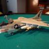
After eight weeks the Revel A-26B Invader is finished. I painted, decaled and installed the propellers, installed the antenna using EZ-line, and did some final touches on the weathering to complete this build. Overall this was a fun build. The kit has a good fit and only minimal putty was required. The kit decals as well as the Kits World decals worked very well. The instructions are laid out well. The added photo etch accessories from Eduard provide very good details and add a level of realism especially in the bomb bay area. The only difficult area was the gunner’s seat assembly. To add the photo etch you need to cut off sections and place them onto the photo etch frame. Cutting them off and aligning them up so the assembly is straight and even took a little bit of time. I hope you have enjoyed following along on this build. Happy Modeling! All the details and photos from the start to finish can be seen in the build log at: https://davidsscalemodels.com/build-log/1-48-a-26b-intruder-maggies-drawers/
-
The seventh week on the Invader has the decals applied and the rest of the details being worked on. The decals were a mix of kit decals and the aftermarket Kits World decals. Both sets of decals worked very well except the stars and bars insignia’s. The kit version looked like the blue ink around the star was too thin of a layer. The Kits World decals were a lighter blue and slightly smaller. I ended up using a set from another aftermarket sheet of insignia’s that are colored correctly and accurately sized for 1/48 scale. I then added weight to the nose. Each engine nacelle has two ounces of weight behind the engine and I added two more to the front of the nose. This was enough weight so the aircraft sits properly on the landing gear. The landing gear was assembled and installed. The kit comes with two styles of wheels. One set was just regular wheels and the second set has a flat side represented wheels with weight on them. I used the latter set. The canopies were then detailed, painted, and installed. I also modified the recognition lights on the underside of the fuselage by drilling them slightly and filling them with acrylic gel. These were then painted with Tamiya clear green, red, and yellow. I still have to finish the weathering and final details to complete the aircraft. Next week I will have the final photos of this build and a preview of the next build. All the details and photos from the start can be seen in the build log at: https://davidsscalemodels.com/build-log/1-48-a-26b-intruder-maggies-drawers/
-
As the sixth week ends on the Invader I spent the week preparing the aircraft for the base coat of paint. I installed the wings and then detailed the bomb bay doors with the photo etch. These were then installed to the fuselage with the photo etch hinges. After I panted and weathered them I then cut the molded wingtip lights so they can later be replaced with clear lenses. One of the unique things about “Maggie’s Drawers” is that it had the loop antenna instead of the teardrop version usually seen on the A-26’s. Since the kit does not have this option I used 30 gauge wire and formed the loop antenna. I used a paintbrush handle and wrapped the wire twice around. After shaped it I coated the antenna with some CA glue to seal it. As I said last week I ordered the metal landing gear struts, these arrived this week so they were cleaned up and painted. I then painted the aircraft with Vallejo Duraluminum. The canopy and upper rear window were then masked and painted as well. The scheme also has a vertical black stripe on the rudder so this was also painted. I also painted the olive drab anti-glare areas on the inboard side of the engine cowls and in front of the canopy. Up next will be the decals. I will be using the kit decals for the standard aircraft and the Kits World decals for the specific scheme. Once the landing gear is installed I can then check the amount of weight I need in the nose and attach the nose. All the details and photos from the start can be seen in the build log at: https://davidsscalemodels.com/build-log/1-48-a-26b-intruder-maggies-drawers/
-
They did not come with the kit. Thundercals makes a nice set of insignia's and placards. Set 48005. Designed for P-47's but the engine and prop logos work on many other aircraft. BUY TCAL DECALS | ThunderCals
-
I spent most of the fifth week on the Invader super detailing the Pratt & Whitney R-2800 double wasp 18-cylinder engines. I started off by drilling the cylinders with a 0.25mm drill and then the ring with a 0.5mm drill. The engines were then painted and I added the Pratt & Whitney logo and engine placard decals. Once painted I then used 30 gauge wire for the lines. I installed them on the cylinder side first then trimmed them to fit into the ring. These were then painted with dark brown. While things were drying on the engine I weathered the main gear bays and installed them onto the wing. I also built up and cleaned up the gun pods for the wings and the main gear struts. Since the tail was already installed I checked out how much weight I will need to install to make sure it rests on the gear correctly. With the weight required it looks like the kit landing struts, especially the nose strut may not support the weight correctly, I decided to replace them and ordered the SAC metal landing gear struts which are scheduled to arrive this coming week. Moving back to the engines I review some reference photos of the exhaust. The kit has them molded inside the cowl. These are too short and too small diameter. I then sanded these all down and replaced them with some 0.75mm styrene rods. The cowl sections were them painted with Vallejo metal Duraluminum paint to represent the NMF finish of the aircraft. The rear section was then weathered with brown, grey, and black pastel chalk to represent the exhaust staining from the exhaust. I also added some weight inside to aid in balancing the aircraft. I am currently working on installing the wings and other external details to the fuselage. I am hoping to get the base coat and possibly the decals completed over the next week. All the details and photos from the start can be seen in the build log at: https://davidsscalemodels.com/build-log/1-48-a-26b-intruder-maggies-drawers/
-
During the fourth week of the Invader build I finished all the interior details and assembled the fuselage halves. Everything fit together pretty good but there are a few areas that required some minor putty along the seams. Since this kit has raised panel lines it took some time to putty and sand the seam areas without sanding down the panel lines. Next I assembled the wings and the main landing gear bays. One thing to note is Revell placed TWO copyright stamps on the port wing. Not only the port inside flap but also on the brace that supports the wing inside the landing gear bay! These were then sanded down and removed. I painted and weathered the bays. I have not attached them to the wings yet as I just found some reference photos of the bays so I can add some more details like cables and lines later. I am now starting on the engines. Since there is not any photo etch details for them I am scratch building the ignition wires. I will be using 32 gauge wires for this and drilling the holes for them using .25mm drills. Hoping to have the engines completed and the gear bays completed so I can mount the wings this coming week. All the details and photos from the start can be seen in the build log at: https://davidsscalemodels.com/build-log/1-48-a-26b-intruder-maggies-drawers/