Wolfman63
-
Posts
629 -
Joined
-
Last visited
-
Days Won
111
Content Type
Profiles
Forums
Events
Everything posted by Wolfman63
-
The seventh week of the F-35C was spent detailing the canopy and preparing all the landing gear, tail hook, weapons bay, and boarding ladder doors. Starting with the canopy I detailed it using the kit photo etch details. After the photo etch was installed I was reviewing the instructions and noticed there was no way to mount the canopy! The instructions do not show or call out the part that mounts onto the front of the canopy to represent the hinge. I looked over the part trees and located the part that looks like a similar part used on the Tamiya F-35 kits and installed it. Next I turned to the wing tip sections. These required some putty to fill the seam in the middle of the flaps. The wings were then mounted onto the aircraft. I should note that the kit has instructions for wings down and wings folded. I opted for wings down. The mounting of the wings down takes some work to mount and align them as there are no guides for them to mount to. I also assembled the small center fuel tank and putty the seams as the fit was not the best. I then began cleaning up all the doors. The first issue is the multiple mold marks on the inside of nearly all the doors. These needed to be filled with putty. The second issue is the two side doors for the tail hook. Only one of the doors had one hinge molded on. The other hinge and both on the other door were not molded on. I located some spare photo etch hinges I had and will use these. The third issue is the weapons bay main doors. The weapons bays have three locations for the main door hinges and the kit has three hinges for each door. However the main doors have four cutouts to mount hinges. The fourth cutout (if it had a hinge) would interfere with the small door in the center of the weapons bay. All reference photos for the “C” show three main hinges and the small door. I filled the extra hinge slot with putty. I am now working on the starboard nose gear door which has some avionics boxes that need to be scratch built and hooked to the wiring I added previously to the nose gear bay. I am hoping to start the painting later this week once all the doors have been installed. You can see all the photos and details from the start in the build log at: https://davidsscalemodels.com/build-log/1-48-f-35c-vfa-86-sidewinders/
-
The sixth week of the F-35C was started off with installing the refueling probe. I then added the kit photo etch details to the canopy rails. According to the instructions there is a piece that mounts to the rear of the canopy area. This piece was missing from the kit. Looks like when injecting the plastic it did not fill in this part of the mold. Using reference photos I scratch built a new part. The canopy tub was then installed into the upper fuselage. I needed to sand down part of the backside of the refueling probe bay to get the cockpit tub positioned correctly. I then went to assemble the upper and lower fuselage assemblies together. The fit was a little on the poor side. The area where the refueling probe bay sits required more sanding to get the fuselage halves to join correctly. Also the lower fuselage was a little off just behind the refueling probe area as well. Once the fuselage was together I assembled the wings and rear stabilizers. While installing the wings the topside fit well but the underside had a gap where it meets the fuselage on both wings. Finally I assembled the tails. The port side tail required some sanding and filing to make it fit correctly on the fuselage. The starboard tail fit much better and only required some light sanding. I am now working on the outside of the wings and then detailing the landing gear doors. I am hoping to get the painting process started by the end of the week. You can see all the photos and details from the start in the build log at: https://davidsscalemodels.com/build-log/1-48-f-35c-vfa-86-sidewinders/
-
For the fifth week of the F-35C I worked on the main gear bays and struts. I used the reference photos to add all the lines to the struts. I used different size wire and some scrap photo etch parts. I also added the tie down loop to strut as well. I then used a reference photo to create the placards for the struts. Next I came across an issue. The directions show assembling the main gear and then installing them in to the lower fuselage assembly. The issue is once the wheels are attached you are unable to install them as the wheels and struts together are too wide to fit thru the gear openings. One of the bays I did not install the wheel yet but I did have to remove the other wheel to install it. I ended up pinning this wheel onto the strut. I then went to make sure the landing gear sat correctly and found out the tail hook was too low. I cut the control strut for the tail hook to raise it up a bit. Now all the landing gear and tail hook sit evenly in the ground. Another issue is the instructions have you install the cockpit assembly on to the topside of the nose gear bay. However during a dry-fit check there are no markings as to the exact location to mount it. I decided to mount the cockpit on the upper fuselage instead. I taped it the cockpit assembly in place on the upper fuselage and did another dry fit check. This will work a lot better for the correct alignment. I am now working on the upper fuselage details starting with the refueling probe and upper intake panels. I am hoping to get the fuselage together next week. You can see all the photos and details from the start at: https://davidsscalemodels.com/build-log/1-48-f-35c-vfa-86-sidewinders/
-
For the fourth week of the F-35C I installed the weapons bays and nose gear bay into the lower fuselage. I then built up the tail hook and installed it as well. Next I started on the engine. Since I am using the ResKit engine I needed to cut off a section of the kit engine from the exhaust side. The resin engine pieces were then painted and weathered. I then assembled and painted the intakes. The kit intakes went together very well and it was easy to hide the seams of the two halves. There were some mold marks that needed to be cleaned up on the inside of them but they were not too bad to smooth out. I am now working on the main landing gear bays. Just like the nose gear bay these lack details which I will scratch build the details. Another thing I noticed in the reference photos are the large placards on the main struts. Neither the kit decals nor the Furball aftermarket decals have them so I will need to make the decals for them. You can see all the photos and details from the start at: https://davidsscalemodels.com/build-log/1-48-f-35c-vfa-86-sidewinders/
-
It has taken a while to get back on track to building models after the big move. There is still a lot of work around the new house like painting, decorating, and updating things. I am spending some time on the bench for a few hours during the week. So the F-35C build is slowly starting back up. Now back to the Kitty Hawk 1/48 F-35C build. I was able to detail the weapons bays this past week. I used 28 gauge wire for the hydraulic lines and fine wires to create the cable assemblies. The kit does not come with the launchers in the bays so I scratch built these based on the reference photos. There were other details in the bays that need to be added as well. With the weapons bays finished I am working on the tail hook assembly then the weapons bays, nose landing gear, and tail hook will be mounted in to the lower fuselage. The engine and intake assemblies will follow. You can see all the photos and details from the start at: https://davidsscalemodels.com/build-log/1-48-f-35c-vfa-86-sidewinders/
-
The first week of the F-35C I installed the seat. The height matches the reference photos and really highlights the cockpit. I added a couple of avionics to the rear deck of the cockpit tub completing the cockpit. I then started on the nose gear bay. I found a really nice reference photo of the F-35C nose gear. In comparing the kit parts I noticed that the kit nose strut is totally different than the actual strut. I was also informed by a representative from Detail and Scale that they did NOT supply reference materials as noted on the kit box. This explains why the details are off. Anyhow, I removed the landing light and the recognition lights from the kit strut. I then scratch built a new landing light and recognition light panel. For the wheel bay I used solid bare wire for the hard lines and 32 gauge black wire for the cables. There are wires that go along the starboard side door so I left some wire sticking up so when the door is mounted I can route the wiring as needed. The strut with the wheels was then installed. Since the kit details are incorrect I located reference photos of them. I also received the Furball decal set this week. You can see all the photos and details from the start in the build log at: https://davidsscalemodels.com/build-log/1-48-f-35c-vfa-86-sidewinders/ Now onto the bad news, there will be no more updates on this build. We are relocating in a few weeks and I started the packing process of the model studio. I have 103 built models, 117 models waiting to be built, and all the benches, shelves, cabinets, paints, supplies etc that all need to be packed. I will be moving them myself to help reduce damage. To see what it takes to move a full hobby studio and set up a new one. You can follow the “Big Move 2026” at: https://davidsscalemodels.com/big-move-2026/
-
This is the Kitty Hawk 1/48 F-35C. I will be using Red Fox 3D decals, Reskit resin exhaust, Furball decals for the VFA-86 scheme, and I also added the Eduard 3D Brassin ejection seat. I started off with the cockpit as usual. I cleaned up the panels to prepare for the Red Fox 3D decals. These look great and fit perfectly on the instrument and side panels. The decal set has the option of the instrument panel display “on” or a blank screen for the “off” mode. I looked at the kit ejection seat and it is not very well detailed. I researched this kit and found some folks noted the kit ejection seat is too tall and if you wanted the canopy closed it will not close because of the seat. I opted to use the Eduard 3D brassin ejection seat. The seat is very detailed and the instructions also offer other details that can be added. Care is required to trim the parts off of the carriers as they are very delicate. There are eleven different parts as well as a sheet of photo etch and decals for all the warning placards. I am currently finishing up the cockpit assembly and details then moving on to the nose gear bay and then the weapons bays. You can see all the photos and details from the start in the build log at: https://davidsscalemodels.com/build-log/1-48-f-35c-vfa-86-sidewinders/
-
The third and final week of the ZL59 Q-Class Airship started off by building the new stands. I used styrene sheets for the base starting with a round bottom and then cutting out a German Flying Cross emblem. A styrene tube for support and a styrene square rod formed to the Q-ship. I also added some foam pads to keep the stands from scratching the surface and to keep the Q-ship form slipping on the stands. These were then painted German Grey with a black and white cross. I raised the height from .5” to 2.0” tall so that the underside details could be better seen. I added the gun mounts to the topside completing this build. This build was a fun build. The kit itself was very good. The photo etch details are tedious to do but look great once in place. I think this kit would have been better if the gondolas had open windows and photo etch frames for the forward gondola green house windows on the nose. The fit was very good and only required a little putty for the main fuselage. The only real disappointing part of this kit was the undersized stands. They are way too small to proper support the model and allow easy viewing of the underside details. The decals worked out very well and applied easily. Aside from the poor stands I would recommend this kit for those who want something unique to display. I hope you all had fun watching this build. Happy Modeling! You can see all the photos and details from the start to finish in the build log at: https://davidsscalemodels.com/build-log/1-350-zeppelin-q-class-airship/
-
The second week of the Q-ship started of good. Built up and attached the out rigger engine mounts. I then began painting the scheme for the LZ59. There are three different colors used in the scheme. The colors listed in the instructions are MIG Ammo paint colors. I have never tried them so I decided to purchase them for this kit. The lightest color is Cremeweiss. The darkest is Dunkelgelb. The middle color is a three parts Cremeweiss to one part Dunkelgelb. After using these paints I am very happy with them. They work very well with either spraying or brush painting. The paint gives you an even coat and covers well. When I did touch-ups with a brush there were no brush marks and you cannot tell what was sprayed and what was brushed. The dried paint is durableI will add these to the list of paint brands to use on future models. To aid in painting I scanned in the painting guide from the instructions and then scaled it to the same size as the model. This allowed me to measure the different sections to correctly mask them. The print out also will aid later when I need to apply the decals to their correct positions. I started with the lightest color first, then the middle color and finally the darker color. Once the painting was completed I installed the gondolas. For the aft gondola I had to attach a couple of more struts that went from the out riggers to the gondola. And this is where disaster struck! The stands that came with the kit are short small clear stands. These are too small for the kit. The airship can easily be bumped and knock the airship off of them. When it rolled off the stands the aft gondola took the brunt of the damage. I spent two nights rebuilding all the supports for the aft gondola and straightened the out riggers. I decided that I will make new stands to better support the airship later. After the repairs I used a little bit of tape on the stands while I applied the decals. I am now working on the stands. I am going to make the curved sections longer to better support the model and also make the stands a little taller. Once the stands are made all I need to do is mount the topside guns to complete the model. You can see all the photos and details from the start in the build log at: https://davidsscalemodels.com/build-log/1-350-zeppelin-q-class-airship/
-
This next build is something different. It is the Takom 1/350 Zeppelin Q-Class Airship. I will be building it as the LZ59 (L20) Airship. The LZ59 after completing its second bombing raid on Britain the airship started having engine problems on its return. This plus the strong winds from a weather front caused the airship to veer north towards Norway. It ended up crashing in the water Jasund, Norway. The first week I worked on the forward and aft gondolas. The kit has all the windows on each one molded in. I decided to open them up. The forward gondola has a large window area on the nose. I ended up using some 32 gauge wire and replaced the kit parts by making my own framing. The top and side windows were then made with small strips of clear acetate. The side windows on both were drilled out and filled with clear acrylic gel. Both of these are held on to the lower panels via lots of small photo etch struts. The forward gondola wasn’t bad as it had the large supports which were access to the inside of the main airship. The aft gondola was a lot more delicate. Getting the struts lined up and placed correctly required some tedious work. With the gondolas mounted to their respective lower panels I started working on the main airship. The Q class ship is similar to the P class ship except for length. The kit is designed for both P and Q classes so this kit has a center section to make it the correct length for the Q class. The fit was pretty close but it still required a bit of putty to cover the seams. I am currently working on the main airship. The airship has a total of four engines. One on each gondola and two mounted on outriggers. These are also mounted with photo etch struts. The struts go to the main body as well as the aft gondola. I should be starting on painting this upcoming week as well. You can see all the photos and details from the start in the build log at: https://davidsscalemodels.com/build-log/1-350-zeppelin-q-class-airship/
-
Week three of the U-505 U-Boat I started off by assembling the display base. The stands were painted gloss black and then I used a gold paint pen to highlight the base of the stand edges. Once they were positioned I used epoxy to attach them to the wooden base. The nameplate was then attached and finally the submarine was attached to the stands. Next I used EZ-Line for the jumping wires. I used some acrylic gel to create the cutters used on the jumping wires and then painted them matte black. This completed the model! In review, working on resin models is interesting. The basic hull just required a little clean up. Most of the build time is adding the fine details. Also CA glue is what is used to attach the details. Regular model glue does not adhere to the resin. Due to the size the photo etch details required small tweezers and a steady hand to get them in place. The kit instructions were very good. The only downside to this kit is there were no mooring cap stands on the deck. Building a resin model is different but this was a fun build for me. You can see all the photos and details from start to finish in the build log at: https://davidsscalemodels.com/build-log/1-350-type-ixc-u-boat/
-
Week two of the U-505 was spent detailing the conning tower with all of the kits photo etch parts. For the periscopes the kit provides brass rods. I use a file to flatten the area for the lens. As I was doing the conning tower I noticed two areas on the side where the resin had sunken in a bit. These were filled with putty. The kit did not supply the ladder rungs for the conning tower so I used some fine copper wire to make the rungs. While the photo etch parts were drying I started to make the pedestals for mounting the submarine. I cut out three different size circles and then used a styrene tube as the post. The tube was notched to fit the keel line on the bottom of the hull. Next I painted the submarine. After a lot of research I opted to paint the U-505 in the original tri-color scheme used on the IXC U-boats. The lower hull was painted Schiffsbodenfarbe III Grau RAL 7016, the upper hull was painted Dunkelgrau 51 RAL 7000, and the conning tower was painted Blauschwarz 58/2. The decks were painted with satin black to replicate the coating they typically painted the wooden decks. The kit does not provide any decals so using the reference photos I made the “seashell” logos used on the sides of the conning tower and the U-Boat logo on the front of the conning tower. Due to the small size I matched the background of the decals to match the Blauschwarz 58/2 paint used on the conning tower. This made trimming and applying the decals easier. I am working on the display base now. The brass etched nameplate from EnM Engraving arrived this week. I just need to sand and finish the wood base. Once the submarine gets mounted I can install all the rigging to complete the model. You can see all the photos and details from start in the build log at: https://davidsscalemodels.com/build-log/1-350-type-ixc-u-boat/
-
About 12 years ago we took the kids to the Museum of Science and Industry in downtown Chicago. We took a tour through the U-505 submarine which was captured by the U.S. Navy on 4 June 1944. Back then I purchased the Yankee Modelworks 1/350 TYPE IXC U-BOAT full resin kit. This sat on the shelf for many years. I decided to finally build it as the U-505. While being full resin there is not a lot of assembly but there is a sheet of photo etches to detail it. I also have some details I need to scratch build and decals to make specifically for the U-505. I will also make a nice display stand as well. To start with when I first purchased this kit there was a huge resin mold base along the bottom of the hull. At that time I used my jewelers saw to trim the base off and sanded the keel line. I started with assembling the rear screws and rudders. The screw shafts are brass rods and the rest is photo etch. I then added the front diving planes. Next I started adding the deck details. One thing the instructions do not discuss is the mooring posts that are present on the deck. I used styrene rods and slightly heated one end to give them the mushroom top. These were then added to the correct locations on the deck per the reference photos. I am now working on the conning tower. While there was no hull assembly since it is molded in resin the deck and conning tower still require some clean up of the details. I used a scribe and hobby knife to do the clean up. There is a couple of small mold imperfections on the conning tower so these were filled with putty. You can see all the photos and details from start in the build log at: https://davidsscalemodels.com/build-log/1-350-type-ixc-u-boat/
-
The third and final week of the Academy 1/48 TOW Defender 500D helicopter build is now completed. To start with I sanded the area around the nose pod and finished all the detail painting. I used EZ-line to replicate the underside antenna line. There are two red lights on the fuselage. One is under the start of the boom and one on the tail. I cut off the molded “lights” and replaced them with clear lenses. These were then painted with Tamiya X-27 clear red paint. The top canopy windows were then tinted green using Tamiya X-25 Clear green paint. There are two side navigation lights on the front of the skids. I drilled these out and filled them with clear acrylic gel and then painted then with the clear red and clear green paint. The TOW launchers were then installed and the additional wiring was hooked to the fuselage. The next step was the decals. The kit does not supply decals for the typical sandy brown paint scheme so I used reference photos and made my own decals. These were applied and a matte topcoat was applied. Finally the main rotor was assembled, painted, and installed. This completed the build. In review, this kit has many fit problems especially around the side door, interior assembly, and nose pod. The kit also lacks a lot of details. The instructions have a good assembly flow. The only kit decals I used were the Israeli Air Force insignia’s on the sides. These went on very well. Overall I would consider this an average kit. I do not think I would recommend this kit mainly due to the fit issues. Granted not all kits are perfect but the fit on this kit was more bad than average. I hope you all have enjoyed following along and if you decide to tackle this kit at least you are aware if the main issues. Happy Modeling! You can see all the photos and details from start to finish in the build log at: https://davidsscalemodels.com/build-log/1-48-tow-defender-500d-helicopter/
-
The second week of the 500D Helicopter I was able to finish and install the interior. I added the interior fuselage details and some interior details with first aid bags in the rear area. The interior assembly was mounted into the port half. The starboard half had some interior detail added and then I installed the door. This is where this kit starts to show its bad fit. The door has a huge gap across the top edge and a small gap on the bottom right corner. I filled the gap in with putty and will re-scribe the door seam later. The upper windows above the doors have a 1mm gap as well. I used acrylic gel to fill this gap. I then put the two fuselage halves together. This is where the fit huge issues rear its ugly face again. The interior assembly has a huge 2mm gap between the fuselage and cockpit floor. The fuselage is what is too wide. To properly mount the canopy I had to make a curved clamp to align the fuselage frame to the center of the canopy so they meet correctly. The top area and bottom area fit pretty well. The landing skids were mounted. Speaking of the canopy, the raised markings for the canopy frame and the forward light bezel are molded on the inside. This makes no sense. For the forward light I used a photo etch part to be the light bezel. After the fuselage issues were corrected I added some of the ducts to the fuselage and added the tail. I then base coat painted the sandy brown paint. I then went to mount the nose pod. This is another part that does not fit very well. I sanded the edge that mounts to the canopy to get the gaps smaller and then I used putty to fill the gaps. I then finally scratch built the mounts for the cable antenna that runs across the underside of the fuselage. I am working on the main and tail rotors now. All that is left are the decals, some more details on the fuselage, and the final top coat on the helicopter. I should have this finished by the end of the coming week. You can see all the photos and details from the start in the build log at: https://davidsscalemodels.com/build-log/1-48-tow-defender-500d-helicopter/
-
For my next build I will be building the Academy 1/48 scale TOW Defender 500D and using the kit decals for the Israeli Ai Force. This kit does lack some details so there will be some scratch building of the missing details. I started off with the pod for the nose. The kit does not provide any details under the lens so I used some styrene to make the inside panel. I used a reference photo to replicate the panel. I then assembled the TOW missile launchers that mount on the sides of the fuselage. The reference photos show cabling from the fuselage thru the wing and into the pod. The kit does not provide this detail but I will add them later once they are mounted to the fuselage. Next I started working on the cockpit and interior. The bulkheads have no details on them. I used some photo etch pieces to add the details. It looks like the inside of the fuselage halves will also need a lot of work due to the large mold marks. Switching over to the cockpit side I added seatbelts to the seats. One big detail that is missing is the cyclic control stick. I used some styrene rod and photo etch to replicate them. The instrument panel has no raised details and a very basic decal is supplied for the panel as well as the center console. I found some nice reference photos and created my own decals of them. The kit foot pedals were huge so I trim them down. I am going to wait to install the instrument panel until after the interior id mounted inside the fuselage. I am currently working on the indie of the fuselage halves. Once the mold marks are corrected I need to use some styrene to replicate the inside ribbing. You can see all the photos and details from the start in the build log at: https://davidsscalemodels.com/build-log/1-48-tow-defender-500d-helicopter/
-
The fourth and final week of the ICM 1/48 Russian U-2/P0-2 project is now finished. I completed all the rigging, installed the windscreens, and mounted the engine. For the rigging I used EZ-Line fine. The nice thing about using EZ-Line is it is very elastic so the lines stay tight but the model can be handles without damaging the rigging. There are two rods that sit in the middle of the rigging between the upper and lower wings which I used thin styrene rods. The windscreens were then installed and the engine was mounted completing this build. This was a fun little build and all the rigging really brings out the realism. As for my review of the kit it was a decent kit. One thing to note is ICM uses a softer styrene so care needs to be taken when removing and cleaning up parts. The under wing skid bars and horizontal stabilizer struts are a little too thick from the kit and very delicate to remove from the tree which is why I replaced them with styrene rods. The decals were good. I just think it would have been better if the kit decals had the side stripes sectioned off for the fuselage details. Some of the attachment points for the rigging like the rudder control and the skis were not on the kit parts. It is weird the kit instructions show the rigging points on the main skis but they are not actually on the part and the rigging instructions show attaching the rigging to them. The rigging guide was very detailed they just did not show the control lines on the wings control surfaces but the attachment points are there so it is just a matter of adding the small lines. I would recommend this kit. Thanks for following along on this small build. Happy Modeling! You can see all the photos and details from the start to finish in the build log at: https://davidsscalemodels.com/build-log/1-48-russian-u-2-po-2/
-
I am using EZ-Line Fine. EZ-Line for rigging. – Davids Scale Models
-
The third week of the U-2/P0-2 I base coat painted the aircraft and painted some of the finer details. I then applied the kit decals. The dual white arrow stripes that run down the sides of the fuselage needed to be cut into sections. This is because the control arms for the horizontal stabilizer are in the middle of one stripe and the other details on the fuselage required the stripe to be notched. Aside from that the rest of the decals went on very well. Next I started on the rigging. The instruction sheet provides most of the details on how to rig the aircraft. I started with the tail section rigging. The rudder and horizontal stabilizer rigging was run along the fuselage. The tail ski also had a bit of rigging as well. The main wings have some small rigging for the control surfaces so these were added. I then moved on to the main landing gear struts and skis. I am now working on installing the main upper wing and then on to the final rigging. Once the rigging is completed I just need to add the windscreens and mount the engine. This will complete this build. You can see all the photos and details from the start in the build log at: https://davidsscalemodels.com/build-log/1-48-russian-u-2-po-2/
-
I use a hobby knife handle to curve the wingtip skid bars.
-
The second week of the U-2/P0-2 was spent building and detailing the engine and adding details to the fuselage. On the fuselage I added all the kit details and the control arms for the moving surfaces. I also modified some details. The kit provides two skid bars on the lower wing tips and the rear horizontal stabilizer. The problem is the kit versions are very thick in diameter and look huge compared to the reference photos. I decided to use some styrene rods to replace these. On the fuselage the control arms for the rudder are just molded slots I added some photo etch to duplicate the control rod ends so the rudder control lines can be added later. On the skis there are rigging lines to help the skis stay in their correct angle during landing, take off, and flight. I added the attachment of these cables to the skis using photo etch as well. Next I started on the engine. The kit provides a piece to represent the pushrods. But these are molded together. I trimmed off the plastic “rods” and replaced these with 30 gauge wire. On the reference photos of the engine the ignition wire that goes to the spark plugs is not represented in the kit. I used 30 gauge wires for the wires and some black wire tubing to represent the connectors at each end of the ignition wires. Moving on to the exhaust, I drilled out the ends to open them up. The kit provides a cowl/cover for the front of the engine. I reviewed many photos of the actual aircraft and only found two photos where this was used. From the photos the two photos were of the wheeled version of the aircraft and appeared to be post war aircraft. The other reference photos that had the ski version did not utilize the cover/cowl so I did not use it. I am now getting ready to start the painting. I will be using Field Green for the topside and light blue for the underside. I will also be painting the white stripes on the wingtips. Once the base coat of painting is completed I hoping to be able to get the decals applied over the next week. You can see all the photos and details from the start in the build log at: https://davidsscalemodels.com/build-log/1-48-russian-u-2-po-2/
-
For my first build of 2026 I will be doing ICM’s 1/48 Russian U-2/Po-2 multi-purpose aircraft. This is a bi-plane that was initially used as a training aircraft and was also used as a liaison, reconnaissance, medevac, and general supply aircraft on the eastern front during World War II. The aircraft was so versatile that it was built from 1929 thru 1959 and used by 16 different countries during it service years. The version I will be building will be early WWII with skis for landing on snow covered fields. I first started off with the cockpit area of the fuselage halves by adding some details like the control levers and paint it. The instrument panels were then painted and I used the kit decals for the instrument faces. The fuselage halves were the put together. While gathering the parts for the lower cockpit I notice the landing light that mounts under the lower wing. I drilled out the kit “lens”, painted it with chrome paint, and created a clear lens from acrylic gel. I then worked on detailing the lower cockpit. The first thing I added was seatbelts to the seats. I then trimmed down the kit rudder pedals and made the foot straps. These were mounted on the lower wing assembly and then this was mounted to the fuselage. I am now working on the engine assembly and adding some details to the fuselage. You can see all the photos and details from the start in the build log at: https://davidsscalemodels.com/build-log/1-48-russian-u-2-po-2/
-
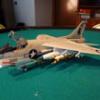
As 2025 comes to a close here is a review of the eight builds completed over the last year. Four of these were commission builds. Three of them were larger projects that took up a lot of time to build to get the details correct for the clients. The first build of 2025 I built was Academy’s 1/48 PBJ-1D (B-25D). The scheme is the “The Fork-Tailed Devils” of VMB-433 for the U.S. Marines located on Emirau Island, New Guinea 1944. I added some resin seats as well as photo etch details to compliment the model. I had to scratch build the boarding ladders and many details in the nose. For a reference I used William Wolf’s “B-25 Mitchell – The ultimate look” book. This covers everything on the B-25 from drawing board to flying arsenal as well as all versions including the PBJ versions. You can see all the photos and details from start to finish in the build log at: https://davidsscalemodels.com/build-log/1-48-pbj-1d-b-25-mitchell/ The second build and the first commission build was of Trumpeter’s 1/25 scale American LaFrance Eagle Fire Pumper Fire Truck was for a client who trained and served as a volunteer fireman on this truck. This was the first time I built a fire truck and interesting build for me. The client also furnished many photos of the actual fire truck. I used some resin accessories from “Three Inches under” as well as scratch built many details like the fire hoses and nozzles, SCBA packs, and custom decals. Below are photos of the completed model as well as a short video of the model on a turntable. You can see all the photos, details, and final video from start to finish in the build log at: https://davidsscalemodels.com/build-log/1-25-american-lafrance-eagle-fire-truck/ The third build and second commission I replicated a 1922 Ford Model T Touring for a close friend whose father recently passed away. The car was his pride and joy as he spent many years restoring it. The problem is there were no 1922 Model T Touring kits available. So after doing some research I found two kits that I used to “kit bash” most of the parts and sections to replicate most of the vehicle and scratch built other specific parts for the 1922 Ford. I used multiple photos of the actual vehicle so it was easy to replicate. This was then mounted in a display case made by Grandpa’s Cabinets. The term “Kit Bash” is a modeling term where multiple parts from multiple kits are used to make a specific model. This was the first time I used the kit bash method to create a fantastic replica for this memorial project. You can see all the photos, details, and a video of the build in the build log at: https://davidsscalemodels.com/build-log/1-25-scale-1922-model-t-touring-car/ The fourth build I used an old kit made by Testors. Testors was known for doing some of the unique subjects over the years. This is their 1/32 scale H-43B Huskie helicopter. It was originally released in 1961 by Hawk Models and re-issued in 1967 to include Viet Nam Era parts. The version I built is the final release of the kit in 1998. I scratch built all of the interior details. The Kaman Aircraft H-43B Huskie is a very distinctive helicopter. It uses twin main intermeshing rotors. These were counter-rotating so a tail rotor was not required. It was first flown in 1953 and was in service until the early 1970’s. During the Viet Nam War it was utilized as an Air Rescue and Recovery helicopter which were part of the Pacific Air Rescue Center. You can see all the photos and details from start to finish in the build log at: https://davidsscalemodels.com/build-log/1-32-kaman-h-43b-huskie-helicopter/ The fifth build I went back to 1/48 World War II aircraft. This build was Tamiya’s 1/48 RAF Mustang III. I used Kagero Decals to replicate the aircraft flown by the Polish Pilot F/L Mieczystaw Gorzula of the 309 squadron based at RAF Andrews Field. This was the aircraft that F/L Gorzula shot down a Me-262 jet fighter on April 9th 1945. The build required some minor modifications to add the dorsal fillet in front of the tail and I did my usual of adding details. I enjoyed this build and am happy with the final results. I would recommend this kit to anyone who is looking to build the RAF version of the Mustang. You can see all the photos and details from start to finish in the build log at: https://davidsscalemodels.com/build-log/1-48-tamiya-raf-mustang-iii/ The sixth build and third commission build was done for a client who requests/schedules a build every year. He was a Harrier pilot for VMA-214 also known as the “Blacksheep”. For this build he requested a build of the famous F4U Corsair the Blacksheep flew and it is set in a diorama of a Pacific Island Airfield. The F4U I used was the 1/48 Tamiya F4U-1A Corsair which is mounted in a custom display case From Grandpa’s Cabinet’s featuring a typical island airfield with a Mini-Art Marston tarmac, a couple of rows of palm trees to line the back of the display, a background behind the trees of a beach/ocean view, and mounts that the client’s squadron patch and his name tag sit. I also used Eduard photo etch details to add to the realism. You can see all the photos and details from start to finish in the build log at: https://davidsscalemodels.com/build-log/1-48-f4u-1a-corsair/ The seventh build and last commission build was a fun little project. I built Hasegawa’s Space Shuttle Orbiter on the Boeing 747 Egg Plane! I built this for a friend who is a fan of the Egg planes. This will sit next to the SR-71 Egg Plane that I previously built for him. It only took a few days from start to finish. You can see all the build photos and details in the build log at: https://davidsscalemodels.com/build-log/shuttle-and-boeing-747-egg-plane/ The eighth and final build was Hasegawa’s 1/48 A-4M Skyhawk. The scheme was that of VMA-214 as they flew out of MCAS Iwakuni during the early 1980’s. I used Eduard’s photo etch set for detailing the aircraft. The scheme decals were a mix of kit decals and Cutting Edge’s A-4M Skyhawk Part 2 decal set. You can see all the photos and details from start to finish in the build log at: https://davidsscalemodels.com/build-log/1-48-a-4m-skyhawk-vma-214/ This has been a good year for some interesting builds. I am already planning and scheduling builds for 2026. Thank you all for following along – Happy Modeling! LINK to photos : https://davidsscalemodels.com/2025/12/27/davids-scale-models-2025-the-year-in-review/

-
The sixth week of this build of the Hasegawa 1/48 A-4M Skyhawk VMA-214 is finished! I started the week off installing the photo etch replace the kit version. The wind screen was then painted and installed. The canopy had a seam down the middle. I sanded the seam down with 1000 grit, then 2000 grit and finally 4000 grit sanding stick. The canopy was then polished. The photo etch latches and the rear view mirrors were installed and the canopy was then painted. I installed the canopy in the open position. For the final assembly I installed the drop tanks and all the mounts on the other hard points. This completed the aircraft. The end result was a very nice looking A-4M depicting VMA- 214 that operated out of MCAS Iwakuni Japan in the early 1980’s. The kit went together very well and had a good fit. The instructions flowed very well. The only negative things about this kit are the decals. They are a little on the thick side which affects the upper wing star/bar insignia due to the surface detail of the upper wing. The tail decal for the rudder stars are one large decal and would be difficult to conform to the rudder details. The aftermarket kit supplied the stars individually which was a lot easier to paint the rudder and apply the individual stars. This was the last build of 2025. Thank you for following along as I get ready to schedule some more interesting builds for 2026. Happy Modeling! You can see all the photos and details from start to finish in the build log at: https://davidsscalemodels.com/build-log/1-48-a-4m-skyhawk-vma-214/
-
The fifth week of the Skyhawk was spent applying the numerous decals. I used a mix of the kit and aftermarket decals. The kit decals provided many of the small placards. One of the advantages of the aftermarket kit was the stars on the tail. These stars were individual decals which were easier to apply then trying to get the kit on piece decals to conform to the decals on the tail and rudder. The aftermarket decals were a little thinner than the kit decals which were better for the topside wing stars and bars. This conformed to the surface details than a thicker decal would. There was also one decal missing from both sets. This was the placard on the inside of the main gear doors showing lift and anchor point on the aircraft. I used a photo I located on Google and made my own decals for the placards. The aircraft was then top coated clear to seal the decals. With all the decals applied I started on adding the final details. I painted the inside of the IR head mounted in the nose with a pearlized blue clear paint to give it a realistic look. The wingtip lights and the other navigation light lenses were installed. I then installed the landing light on the inside edge of the main landing gear door. I also assembled, painted and applied decals to the drop tanks. I am working on the HUD and canopy details now. The main canopy section has a seam down the middle. I need to remove the seam and then polish the canopy. I will complete this build later this week. You can see all the photos and details from the start in the build log at: https://davidsscalemodels.com/build-log/1-48-a-4m-skyhawk-vma-214/