Wolfman63
-
Posts
624 -
Joined
-
Last visited
-
Days Won
109
Content Type
Profiles
Forums
Events
Everything posted by Wolfman63
-
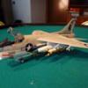
The third week of the Mirage was spent painting the camouflage and then applying the numerous decals. As for the camouflage I used Light Ghost Grey for the lighter color. As for the blue grey I sampled numerous paints. I painted a color board with stripes of Model Master Intermediate blue, Vallejo intermediate blue, Vallejo French Mirage Blue, and Model Master Acryl intermediate blue. I then compared these colors to the reference photos of Mirage 2000C’s from the same time period as the client’s aircraft. I settled using the Model Master Acryl Intermediate blue. It was a little lighter and slightly greyer hue than the other intermediate blues. It was also slightly lighter and a little bluer than the Vallejo French Mirage blue. The Vallejo French Mirage Blue color actually is more of a match to the French Mirage paint schemes during the later years of the reference photos. The nose cone was painted Dark Gull Grey which matched the nose cone color of the early Mirage 2000C’s. The inside of the landing gear bays were then painted with light gull grey. After the painting was completed I then started applying the numerous decals starting with the underside first. One of the changes I did was to make decals to change the aircraft number to match the client’s reference photo. While the decals were drying I then painted and applied decals to the Magic II missiles. A quick note on the underside stores, I was informed the Mica Missiles were not used on the 2000C versions so I did not use these. The second thing is this aircraft is going to be in a display case with a background of the client’s photo. The photo shows him standing next to the actual aircraft he flew which did not have drop tanks installed. In order to match the aircraft and allow a better view of the background the client and I decided not to install the large drop tanks. Moving forward I applied all the topside decals. Once dried I then applied the matte topcoat on the aircraft and the missiles then finally installing the engine exhaust. I am now working on adding the other details like the refueling probe, HUD, detailing and installing the landing gear, and the detail painting on the aircraft. I can then start working on detailing, painting, and installing the canopy and windscreen. I should have the aircraft completed over this upcoming week and then I can start working on the display base and the case background. You can all the photos and details from the start in the build log at: https://davidsscalemodels.com/build-log/1-48-mirage-2000c/
-
The second week of the Mirage build was spent assembling the fuselage details. I assembled the intakes and the wing assembly and set them aside for now. The tail was installed and I began adding details to the fuselage like the antennas and pitot tubes had to be modified. This kit has some issues. Aside from the flash and mold marks many of the mounting holes are larger than the pin or tab that fits into them. For the items on the nose I filled the holes with putty then reopened them up to the correct size and I replaced the plastic small blades with photo etch as the kit parts were very thick and the tree stub flowed into the part. For the blade antennas I centered them and then filled in the sides of the slot with putty. I then installed the wing assembly. Again more modifications were required to fit the wings to the fuselage. The starboard side wing root had a large gap which required a shim and putty to fill. Next I worked on the exhaust which was painted using Vallejo Metal paints. The base is “Jet Exhaust” and the highlights are “Exhaust Manifold” and “Burnt Metal”. It was them weathered with light gray, dark gray and black pastel chalk. The landing gear struts were then detailed as well as the wheels. Again I had to fill in the large holes of the nose wheels and re-drill them to the correct size for the strut pins. The missiles and drop tanks were then assembled. Finally I had to modify the nose. The kit comes with the plastic tip but trimming it from the tree weakened it. I accidently broke it twice, first when I added the weights to the nose and then again when I went to paint it. I decided to use a thin brass rod and to replicate the tip I used solder. I am currently getting ready to start painting the aircraft. The underside and light color of the camouflage is Light Ghost Gray. For the blue/gray I am looking at various paints. I will discuss further into this next week once I chose the color that best matches the references I have. You can all the photos and details from the start in the build log at: https://davidsscalemodels.com/build-log/1-48-mirage-2000c/
-
Welcome to the last commission build of 2024. For this build I will be using Kinetic’s 1/48 Mirage 2000C kit. The scheme will be the French version. The client is a Harrier pilot who was doing a joint exercise with France and had the chance to fly one of their Mirage 2000C aircraft. The aircraft will be displayed in a case and the background of the case will be a photo of him standing in front of the aircraft he flew. The aircraft will be detailed using a ResKit resin ejection seat and the rest of the cockpit will be detailed using Quinta Studio’s 3D decals. I started this build by detail painting the resin ejection seat. The seat came with all the warning decals as well. In roder to fit the resin seat into the cockpit tub I had to remove the mount for the kit seat. I then sanded down the side panels and the instrument panel so the 3D decals can be applied. The tub and instrument were painted black and then the decals were applied. The completed ejection seat was then installed. Next I prepared the fuselage halves so I could install the cockpit. The 3D decals also came with the side wall decals as well. With the fuselage halves cleaned and detailed I installed the cockpit and the nose gear bay then closed up the fuselage halves. The fuselage required some minor putty in a few areas due to fit and clean up. I am now working on detailing the fuselage and the intakes then move over to assemble and detail the wings. You can see more photos and details in the build log at: https://davidsscalemodels.com/build-log/1-48-mirage-2000c/
-
After six weeks the Academy 1/48 A-10C of the “flying Tigers” is finished! The week started off mounting the aircraft to the display base and wiring the lights and switch to the battery. Next I installed the canopy in the open position and the boarding ladder. The nameplate arrived a few days later. This was the final thing to be installed on to the display base. In review this kit was one of the better A-10C kits I have built. The detail and fit of parts were excellent. The instructions are well done and the decals are very nice. The only parts that were a little difficult were assembling the engines into the engine nacelles. I would say it is worth the trouble to having one piece nacelles. The other was the windscreen to the fuselage. The fuselage side is thinner walled than the windscreen so a little putty was required to fill in the difference. The one piece rear section of the fuselage was a nice feature and it worked well for adding the lighting. Overall I would recommend this kit for someone looking to build an A-10C. Thank you for following along, Happy Modeling! You can see all the photos, a video, and details from start to finish in the build log at: https://davidsscalemodels.com/build-log/1-48-a-10c-75th-flying-tigers/
-
The fifth week of the A-10C I worked on cleaning up, painting, and applying decals on the weapons. For the AIM-9 missiles I trimmed the nose off and made the IR sensor using acrylic gel. I painted then nose after trimming using chrome silver and I also painted the nose area on the maverick missiles as well. The acrylic gel was then applied to the nose of the AIM-9’s. I also installed the clear nose to the maverick missiles as well. All of these were then painted with Tamiya smoke to tint them like the nose lens of the missiles. On the Litening pod I painted the inside of the turret chrome silver then painted the lenses using Tamiya clear yellow and clear blue. On the actual Litening pod there are a couple of screens on the tail. I located some photo etch screens and replicated these. I then used the photo etch set to install the HUD in the cockpit. The windscreen was detailed, painted and installed. For the canopy what I thought was a seam was actually the molded canopy antenna. I then added the photo etch details and mirrors to the canopy. I will be installing the canopy in the open position so I am going to wait until the aircraft is mounted to the display base before the installation. Finally I installed all the missiles, bombs, rockets, and pods to the underside of the aircraft. Next I started working on the display base. I positioned the aircraft and then drilled the holes for the wires and the front wheel which will be pinned down. I then made a battery holder which will hold the 9V battery to power the lights. I then needed to figure out where to mount the switch. The display base has a thick ring around the edge. Due to the thickness and height it would be difficult to drill out for the switch. The display base will have an etched nickel nameplate mounted onto it so I decided to create an angled plate to hold the nameplate. The mount will also house the switch on the backside. I used some sheet styrene to make the mount. The nameplate was ordered and should arrive early next week. Finishing up the display base I painted the edge with gunship gray and the surface was a base coat of gull gray and a mixture of camouflage gray, medium gray, dark earth, and sand yellow to replicate a tarmac in Afghanistan. So for the sixth and final week I will be installing the aircraft to the base and finishing up some minor details of paint and weathering. Then I will complete the wiring and finish this commission build. You can see all the photos and details from the start in the build log at: https://davidsscalemodels.com/build-log/1-48-a-10c-75th-flying-tigers/
-
The Forth week of the A-10C the engine nacelle was detailed and installed. I used Vallejo Metal Paint Jet Exhaust for the exhaust and Vallejo Metal Paint Duraluminum for the intake. Having the nacelle assembly in one piece makes it nice not having to worry about seams, however installing the engine assemblies are a little tricky when it comes to gluing the upper support. I used a thin brush to glue the rear section in. I then painted the aircraft using Light Ghost Gray, Dark Ghost Gray, Gunship Gray, and some flat Black. Next I began applying all the decals. The kit decals are nice and thin. The good news is they lay down and the surface details shows thru just fine. The slightly less good news is the larger decals have a tendency to fold under. Once the shark mouth decals had dried I painted the gun housing black for the mouth. When painting I covered the lights using Microscale’s liquid mask. After I prayed a clear dull coat to seal the decals I removed the masking and performed a light check. All good! I am now working on the various weapons and pods for the under stores. Once these are finished I will then assemble the canopy and windscreen. It looks like the canopy has a mold seam along the top so I will need to remove it and then polish the canopy. I should have the aircraft completed this upcoming week and then I can start on the display base which will house the battery and a switch to turn the lights off and on. You can see all the photos and details from the start in the build log at: https://davidsscalemodels.com/build-log/1-48-a-10c-75th-flying-tigers/
-
The third week of the A-10C I installed the wings and tail assembly. Before I get into the work completed this week I few reach backs. First I neglected to add a photo of the cockpit installed into the fuselage showing the ejection seat details. The second was a correction. I originally had red flashing beacon lights on the topside and underside of the fuselage. I had a few fellow modelers and one Veteran who also worked on A-10’s let me know that these lights are actually white lights and they do not flash similar to the rest of the navigation lights. Since these both use fiber optic lines I was able to remove the red flashing LED and replace it with a white LED. Now for this week’s work, all of the wiring was routed to the section under the engines I then ran wires from the wire bundle thru each wing thru the landing gear bays, down the landing struts, into the wheel hubs, and finally exiting out thru the tires. These will then be routed through the display base and hooked to the power switch and battery. The nose was modified so the brass gun barrels could fit correctly. The brass gun barrels are also more accurately sized for the 1/48 scale. The kit version is a little shorter in length. The nose was then installed along with the main gear struts. The wires for the lighting were attached to the struts replicating the hydraulic lines. I then installed all of the hard points for mounting all of the weapons later. I am now working on the base coat of paint. I started on the bottom with Light Ghost Grey with a Gunship Grey oval around the nose gear bay. Still have some more detail painting then I can work on the topside Light Ghost Grey and Dark Ghost grey scheme. Once I finish the base coat I will move onto the deals. You can see all the photos and details from the start in the build log at: https://davidsscalemodels.com/build-log/1-48-a-10c-75th-flying-tigers/
-
The second week of the A-10C I was able to get the forward fuselage together. I also added a couple of lead weights so the aircraft will sit on the landing gear correctly. Part of the forward fuselage is the lower panel and the upper panel behind the cockpit. Both of these panels have flashing red lights. The kit does not provide clear parts for the light lenses. I trimmed off the plastic of the lenses and used .75mm fiber optic lines to make the lenses. I then made an optical driver for these. This allows both lights to flash in sync. While the optical driver was drying I looked at the tails. These have two navigation lights. Reviewing reference photos the lights do not shine outward but rather upward to shine across the outside surface of the tails. Instead of using fiber optics I cut odd the molded lights and drilled thru the tail. This allowed me to use PICO LED’s and aim them upward. The light housing was then made out of acrylic gel. With this section painted black and then a top coat of dark ghost grey so the LED only shines upward. The final effect matches the reference photo. Moving back to the forward fuselage the optical driver for the flashing lights was then mounted inside and the panels were mounted onto the forward fuselage. One of the nice things about this kit is the aft fuselage. It is one piece which makes routing wires easier. I routed all the wires from the front to the open section that the engines will mount to later on. The next step was to add the wing tip lights. This was the second challenge. The wing tips curve down on the aircraft. Due to angles I could not use fiber optics to illuminate the wingtip lights. Just like the tail lights I cut out the molded lights and installed the red and green wingtip lights into the wingtip and again used acrylic gel to make the lenses. A small channel was filed to route the wires into the wing. I then applied a thin coat of putty to the backside and sanded it flush making the LED and wiring hidden from the inside view. The wiring was routed along the inside of the wing. I then added the power lines through the main gear bays. These wires will look like the hydraulic lines down the landing gear struts and go into the wheels and come out the bottom of the tires which will go to the battery inside the display base later on. I then assembled the wings and added the photo etch details for the CHAFF blocks. Finally I cut off the aft navigation light and used a .75mm fiber optic line to create the lens. I then used a small diameter styrene tube to make the optical driver and house a PICO LED. I am now working on assembling the wings onto the fuselage and get all the wires routed to one location under the engines. I need to then detail and install the main landing gear and then finish up the wiring then I can start adding the finer details to the aircraft fuselage. You can see all the photos and details from the start in the build log at: https://davidsscalemodels.com/build-log/1-48-a-10c-75th-flying-tigers/
-
A #11 scalpel and sone fine small files.
-
This next commission build is another A-10. I will be using Academy’s 1/48 A-10C “75th FS Flying Tigers” kit. The scheme will be how this aircraft looked in 2014. I will be adding Eduard photo etch detail set, Master Model brass gun, Ares resin ejection seat, and I will be using eight LED’s and some fiber optics to illuminate the aircraft. It will be mounted on a wood base with a hidden battery and switch to turn the lights off and on. The LED’s are from Evan’s Design and are their PICO size LED’s one of which is a flashing red. This will be for the upper and lower lights of the fuselage. The LED will hook to two fiber optic lines so the flashing lights will flash together. I started off building the nose gear bay. The kit bay is very detailed and very close to the reference photos. The strut itself was modified using the Eduard photo etch set. The nose gear strut has two landing lights mounted on it and the kit has them as separate parts. I drilled out the lens portion. I then cut a small slit along the bottom for the wiring. The PICO size LED’s fit perfectly inside the light housing. These were glued in using acrylic gel and then the clear lens from the kit was attached to the front. The lights were then mounted to the strut and the wiring was then routed up and through the rear bulk head when I installed the strut into the bay. I also added some detail wiring on the strut and the nose wheel. Next I turned to the cockpit. The Eduard set includes all the panels for the cockpit tub and the instrument panel. I cleaned up the tub and instrument panel then painted and applied the photo etch. I am working on the Ares resin ejection seat now and then I can assemble the forward section of the fuselage. You can see all the photos and details from the start in the build log at: https://davidsscalemodels.com/build-log/1-48-a-10c-75th-flying-tigers/
-
After four weeks the A-10A of the 75th Fighter Squadron is finished. The start of the week I completed the Litening pod and installed the boarding ladder, HUD, canopy, and windscreen. I did the final paint touch-ups as well. One of the biggest touch-ups was the top of the tails. The decals were a little undersized so I used some Vallejo dark blue which matched the decal color perfectly. As a final step all the under wing stores were installed. Next I painted the display base to represent the tarmac of a middle-east air base. This was weathered with some grime and a few shades of sand, yellow, and tan. The reference photos also had a black with white dashes as a foul line of the taxiways. With the base finished I scratch built some wheel chocks and attached the aircraft to the base. A small stand was made to hold the brushed nickel nameplate and it was then attached to the base. This was a fun project and the kit was a good kit for a 1/72 scale aircraft. The fit was very good and the decals were great. This will be delivered to the client next week. Thanks for following along, Happy Modeling! You can see all the photos and details from the start in the build log at: https://davidsscalemodels.com/build-log/1-72-a-10a-from-operation-iraqi-freedom/
-
As the third week of the A-10A finishes I completed the base coat of paint. I then worked on the landing gear. For the nose gear there are two landing lights. These were just molded flat. O drilled them out a bit and used acrylic gel to create the landing light lenses. The landing gear was assembled with the landing gear doors then everything was installed on to the aircraft. I also installed the brass gun barrels under the nose. Next I applied all the decals. The decals all went one very well. The aircraft was then painted with the matte top coat. While the air craft was drying I turned back to the weapons. I received a comment for a fellow modeler and veteran who worked on the A-10’s on what the typical load out was on them during Operation Iraqi freedom. The weapons supplied in the kit are not very accurate. SO I will be using only two of the Maverick’s, two JDAM’s and will be adding two AIM-9 missiles. The AIM-9’s are resin versions from ResKit. Instead of the ECM pod I am going to add a Litening Pod. This was not available back then but the pod has a connection to the client so I am adding it and using the Eduard resin accessory. I trimmed the nose off the Mavericks to make the sensor heads using acrylic gel. I then filled the lenses on the Litening pod turret with acrylic gel and later will color them the correct shades. I am now working on finishing up the aircraft. The canopy, HUD, windscreen, and a couple of other touch ups and then I can install the weapons. Once the aircraft is finished I will be starting on the display case over the next week and hope to have this build completed by end of week. You can see all the photos and details from the start in the build log at: https://davidsscalemodels.com/build-log/1-72-a-10a-from-operation-iraqi-freedom/
-
The second week of the A-10A was spent getting the aircraft ready to paint. To start with I had to drill out the gun shroud to fit the Master Models brass gun barrels. I then painted the barrels and the housing with Tamiya’s X10 gun metal. I then assembled the wings and added all the hard points on the underside. The brass pitot tube was installed into the wing as well. The engine section was assembled. I had to do a lot of filing on the exhaust. The kit exhaust was very thick so I thinned the exhaust. The exhaust section was then painted using Vallejo’s Jet exhaust Metal paint. The engine pods did require some putty on the outside seams. While some paint and putty were drying I started looking at the armament. It is nice that all the bombs and missiles are one piece however there are a LOT of deep mold marks. On the Maverick missiles I cut off the nose so I can make the lens and I drilled the tail end to match the rocket exhaust. All of the mold marks on the armament were then filled with putty. I then attached the nose, wings, and tails to the fuselage as well as other details. I need to install the engines and then I can start painting the fuselage base coat of paint. I am finishing the painting of the engine intakes, cleaning and painting the weapons, landing gear, and some of the finer details. I should have everything painted this upcoming week and the start applying the decal. You can see all the photos and details from the start in the build log at: https://davidsscalemodels.com/build-log/1-72-a-10a-from-operation-iraqi-freedom/
-
This second commission build is the Academy 1/72 A-10A from “Operation Iraqi Freedom” I will be using the kit decals for the aircraft from the 75th Fighter Squadron of the 23rd wing. This will also be mounted in a display case. It will be mostly “out of the box” build with the exception of using Master Model’s brass gun barrels and pitot tube. I started the week off by assembling and detailing the cockpit. I used some scrap photo etch parts for the ejection handles, some other details, and some 3M cloth tape to make the seatbelts. The cockpit tub, the nose gear bay walls and the engine housing all had some rather deep mold marks which required putty to fill. The cockpit was attached to the nose gear bay section and mounted into the fuselage. The fuselage had a few areas requiring putty as well. The fit was pretty close but some areas had minor gaps. This was prevalent on the top side of the nose. While the putty was drying on other sections I measured the brass gun barrels housing and drilled out the barrel shroud just under the nose to fit the barrels inside the shroud. I am currently building up the wings, tails, and engine assembly. I should have the aircraft mostly together so I can the base coats of the light ghost grey and dark ghost grey of paint. You can see all the photos and details from start to finish in the build log at: https://davidsscalemodels.com/build-log/1-72-a-10a-from-operation-iraqi-freedom/
-
In just four weeks the P-3C Orion of VP-8 “Flying Tigers” is now finished. After many tedious hours of carefully applying the kit decals I was able to get them all on with only some minor issues. The biggest issue of the decals was the upper wing walkways. It seems the grey ink was affected by the top clear coat. It was actually kind of weird it was just the grey areas. These shriveled a bit. I used a few coats of Microscale solvent and they finally settled down to the surface again. With the top clear coat sealing the decals I removed the canopy masking. The underside light was just molded in the plastic so I trimmed it off and replaced it with a clear lens and painted it with clear red. The upper light was not even represented in the kit so I made it from some clear styrene rods. Next I installed all the side windows, engine exhausts, and the propellers. I use EZ-Line for the antenna wires from the tail to the top of the fuselage and this completed the aircraft. For the display base I started with a 16” round base and painted it medium grey. I then misted some light grey and dark grey paint to represent the cement of a flight line. The expansion joints in the cement were made using a dark grey detail pencil. I then used pastel chalk to highlight the lines and stains along the surface. The backside was covered with a sheet of HO scale grass mat to match the reference photo of the actual aircraft. I then added an aluminum etched nameplate listing the aircraft, squadron and location as the final step in this build. This build was an interesting build. For the age of the model it went together very well. The only issue was the decals being brittle from age and the weird reaction to the clear coat on the grey walkways. If you are looking for a nice P-3 the Hasegawa kit is nice. I would recommend a newer edition so the decals are not as brittle or use aftermarket decals. This project is scheduled to be delivered to the client next week. I hope you have enjoyed this build and thanks for following along. Happy modeling! You can see all the photos and details from start to finish in the build log at: https://davidsscalemodels.com/build-log/1-72-p-3c-orion-of-vp-8/
-
This is kind of the third week of the Hasegawa 1/72 P-3C Orion build. The “kind of” is because there was no update last week. My Wife and I went away to a friend’s cabin for a few days to celebrate our 31st wedding anniversary. Prior to our trip I was able to finish the base coat of paint. The landing gear was then assembled, painted, and installed. On a side note I installed weights under the cockpit and inside the nose so that the aircraft sits correctly on the landing gear. Next I scrounged thru my spare photo etch box and located numerous blade antennas. The reference photos show many around the aircraft. One on top of the tail, five on the underside aft, five on the underside forward, one on the spine just forward of the tail and two above the cockpit. After our return I did some minor painting on the top of the tail and the MAD boom. At this point the aircraft was ready for decals. I started by placing the VP-8 specific decals on the aircraft. I then started adding the kit decals and found out that the kit decals are extremely fragile due to the age of the kit and decal sheet. The smaller decals seem fine however the larger ones take a lot of time to get them placed correctly. I am using Microscale’s liquid decal film on the larger decals to aid in keeping them from falling apart. I have noticed some of the smaller decals like the rescue arrows, prop warning stripe, and various placards are also slightly off register so I am going thru my spare decal binder and looking for some replacements. The placing of these fragile decals is a very tedious task. Once I get to the underside decals I will install the landing gear doors. I still have the display base to detail as well. The goal is to complete this by the end of next week. You can see all the photos and details from the start in the build log at: https://davidsscalemodels.com/build-log/1-72-p-3c-orion-of-vp-8/
-
For the second week of the P-3C Orion I masked and base coat painted the fuselage with the white over gull grey paint scheme. I used kapton tape to mask off the windshield and the fuselage. While the white was drying, I built up the propellers and painted them to match the reference photo. I then installed all the under wing hard points and the two inboard pods and attached the wings to the fuselage. For as old as this kit is the wings to the fuselage was an excellent fit. The white sections were masked off on the aircraft and the gull grey base coat was applied. The nose was painted black and the latches were painted gull grey. I then spent two nights creating and scaling the specific VP-8 scheme decals. I had a difficult time locating the tail logo but I was able to use a reference photo and recreated the tiger head. I am unable to print in white so the grey area will be printed on white film decal paper then trimmed with w hobby knife. I went to apply the propeller decals and realized the kit decal sheet had a section that was slightly off register. (Colors not aligned within a single decal) so I made the propeller manufacturer decals as well. The propeller decals were then applied and the top coat of clear was done. I am currently working on the landing gear and the bays. The bays have very limited details so I will be adding some. Also the landing struts and the wheels have a lot of mold marks so these needed to be filled with putty. I plane on getting the landing gear installed and then I can start applying all the decals. You can see all the photos and details from the start in the build log at: https://davidsscalemodels.com/build-log/1-72-p-3c-orion-of-vp-8/
-
NEXT UP – Hasegawa 1/72 P-3C Orion – Commission Build! For my next build and the first of a few commission builds I will be building the Hasegawa/Minicraft 1/72 P-3C Orion. The P-3C is an anti-submarine warfare patrol aircraft for the U.S. Navy. The scheme of this build is that of VP-8 known as “The Flying Tigers” when they were stationed at NAS Brunswick (Brunswick, Maine) during the early 1980’s. This is being built for a U.S. Navy Veteran who served with this squadron. All the details will be scratch built and the squadron specific decals will be made by me. Starting off on the cockpit I needed to first fill in some mold marks on the seats and the cockpit floor. For the seats I used some 3M cloth tape to create the light tan seat pads and the dark grey seat belts. The kit supplied decals for the instrument panel and center console. However these were just outlines of the gauges and control boxes. I made a template of the decals and painted the background with the various colors so when the decals were applied the color was correct. The kit allows for two different versions of the nose cone. The solid one and the other version has a small canopy on the underside. The scheme I am doing has the solid nose so the instructions call out to fill the void with putty. Due to the size of the void I applied putty in layers so that each layer cured correctly. I also added two weights behind the cockpit assembly and one in the nose so that the model will sit correctly on the tricycle landing gear. The fuselage was then assembled. Surprisingly for such an old kit the fit was very good. I then assembled the engines and main wing. The propellers all had mold marks on the backside which required to be filled with putty as well. The only portion of the aircraft that gets painted white is the middle and topside of the fuselage. I installed the windshield which also fit very well. I then began using kapton tape to mask off the windshield sections. I am now working on masking off the areas so I can spray the white section. I still need to clean up the wings and engines so they can be installed onto the fuselage. Then I can mask off the white areas and spray the gull grey. I am also working on the squadron specific decals that I will need to make. I am also going to make a copy of the kit decals just in case I have issues. The kit is from 1979 and the decal sheet looks its age. If the decals start to break apart (especially the larger ones) I will be able to create new copies. You can see all the photos and details from the start in the build log at: https://davidsscalemodels.com/build-log/1-72-p-3c-orion-of-vp-8/
-
After nine weeks the 1/48 Hobby Boss YF-23 ATF is complete. To start with I finished the base coat painting on the topside and the exhaust ducts. I weathered the exhaust ducts with some pastel chalk using black, dark grey, and dark yellow. The Caracal decals were then applied for the PAV-2 scheme. With the decals added I then added the small blade antenna under the nose and painted it international orange to match the reference photos. I also added the light on the top of the spine just forward of the blade antenna. Next I scratch built and detailed the canopy. I used photo etch mirrors on the front edge and then using sheet styrene I built the rear canopy deck. I used some photo etch to make the canopy locks and styrene rods for the canopy lift. A little bit of wiring and the canopy was ready to be installed. I installed the kit HUD and windscreen. This was the last addition to make the build complete. I added the model onto a round base because of where I plan on displaying the model. This build was an interesting build. The kit itself has some detail issues like the antennas, no option to make the canopy open, and no open bomb bay. The fuselage shape is off as well. The Caracal decals do provide accurate decals however the decal film is a little thick. Once the aircraft was top coated the clear areas of the decal film seemed to darkened a bit. The kit instructions are laid out very well and in the end I am happy with the end result. Thank you for following this build and happy modeling! You can see all the photos and details from the start to finish in the build log at: https://davidsscalemodels.com/build-log/1-48-yf-23-atf-black-widow-ii/
-
Eighth week of the YF-23 I had minimal time on the bench. I had some other things to take care of as I will be attending the 2024 IPMS Convention in Madison Wisconsin. I worked on the landing gear and started with a base coat of the fuselage painting. Starting with the port side main landing gear I opted to use the kit pieces. I have had a few folks tell me that the metal main struts due to the angle and weight of the model over time tend to sag. After reviewing the reference photos I made the main gear ID plate decals and then I used some 30 gauge wire for the hydraulic lines on the strut. The port gear assembly was then installed into the fuselage. The nose gear I did use the metal strut. After some minor clean up I installed the nose gear. I did have to add some plastic to the flat side of the metal strut ad the mounting hole was a little larger than the tab on the metal strut. For the fuselage I found some photo etch blade antennas. One went on the spine and the other was mounted on the underside near the fuel dump outlet. I then base coat painted the fuselage and tails with the Light Ghost Grey paint. The tails and the underside were then camouflaged with the Dark Ghost Grey. Since I am using the Caracal decals I used their paint guide which matches the reference photos. One thing to note is the reference photos of PAV2 show a section on the underside between the intakes also had a Dark Ghost Grey patch. However, some of the photos do not show it painted. I am looking up some of the sources to find out when this was added or removed during the flight testing. From the reference book it looks like it may have been added sometime after initial flight test. There is a photo of it during first flight that kind of looks like it was not there and later in the book when they did the mid-air refueling testing along with the YF-22 it was there. I have not decided if I will add it yet or not. I still have the topside of the fuselage to paint with the Dark Ghost Grey so I will decide then. Right now I am working on the starboard side main gear and then I will detail the landing gear doors. Another thing to note is on the inside of the nose gear door one aircraft had “SPIDER” on it and the other had “Grey Ghost” Caracal states the SPIDER was on PAV2 and Grey Ghost on PAV1. I would have thought that PAV1 being the dark grey with the red hour glass would have been Spider and PAV2 with the Lo-Vis scheme would be Grey Ghost. I need to look thru the book and verify this. Caracal does provide both. Actually Caracal provides enough decals to do BOTH aircraft in case you want to build both versions. You can see all the photos and detail from the start in the build log at: https://davidsscalemodels.com/build-log/1-48-yf-23-atf-black-widow-ii/
-
The seventh week has the YF-23 fuselage together. To start off I should note that the instructions state to install the cockpit assembly to the lower half. Due to the modifications to the cockpit tub it was a lot easier to align and install the cockpit tub to the top half. I then assembled the two halves together. There are a lot of small gaps along the edges especially large were the underside of the tail. The nose had some minor gaps as well. The intake and exhaust was very good and lined up well. I used Tamiya fine white putty to fill these gaps. Once dry I wet sanded the areas with 600 grit sandpaper. While the putty was drying I assembled the wings and tail. The wings also had a large gap on the underside as well. More putty and sanding. The tails had no fit issues. The tails just press into the fuselage without glue and they fit just fine. The tail pivot points are very good. There is no slop in the fit so they can move without any wobbling. Next I installed the wings to the fuselage. The topside fit was good with only some minor putty. The port side on the bottom was not bad as well. However the starboard side had a gap along the entire edge. I the re-scribed the panel lines and scribed the lines for the moveable surfaces (flaps, slats, ailerons, etc.) a little deeper to define them better. I am now adding the finer details onto the fuselage like pitot tubes and antenna’s. I then need to mask off the cockpit, landing gear bays, intake, and exhaust areas to start painting. The scheme for PAV2 is light ghost grey with dark ghost grey camouflage. I need to also make a couple of masks for the exhaust area. The exhaust area has a lot of small panels and the reference photos show many panels vary in color. Should have all the painting completed over the next week and possibly starting the decals. You can see all the photos and detail of this start in the build log at: https://davidsscalemodels.com/build-log/1-48-yf-23-atf-black-widow-ii/
-
I use super glue as well but I apply it with a small tipped Glue Looper. Photo Etch Tools – David's Scale Models (davidsscalemodels.com)
-
The sixth week of the YF-23 was spent getting ready to assemble the fuselage halves. The exhaust ports were detailed using some photo etch pieces and some styrene rods. The photo etch was used to detail the flap for the exhaust. On the reference photos there looks to be heat tiles on the bottom of the exhaust port. To replicate these I used some styrene rods glued together then I sanded the assembly to decrease its thickness and give the bottom a flat surface. Next I assembled the intake ducts after painting them white. It is nice that the seams of the halves are at the edges of the duct which makes it easy to fill, sand, and paint. I then installed the main gear bays. With all the vents opened up I started adding the screens. To get the screen mesh trimmed I used a sheet of paper to trace the edges then used that as a template for the screen mesh. The tricky one was the one right behind the canopy due to the zigzag pattern and size. Once installed, that completed all the upper screens. I am working on the lower screens now and then installing the cockpit tub. I am hoping to have the fuselage halves together this next week even though we have some plans over the 4th of July weekend. You can see all the photos and detail of this start in the build log at: https://davidsscalemodels.com/build-log/1-48-yf-23-atf-black-widow-ii/
-
Week five of the YF-23 I am working on the fuselage details. I finished off the main landing gear bays and then started on modifying the fuselage. I began by cutting open the upper fuselage vents above the engines and the spine. Moving forward I drew the correct vent just behind the canopy. This is not marked on the kit. They do provide a decal but the decal is the incorrect size and shape. Switching to the lower fuselage I corrected the panel lines just aft of the bomb bay doors. The kit has the aft edge with the sharp angle scallop when on the actual PAV 2 they are straight. I filled the kit panel lines with putty then re-scribed the correct lines. Next I cut open the engine vents and drilled the fuel dump port. I used aluminum tubing to replicate the actual dump tube on the aircraft. I am currently starting to detail the exhaust. There are many small details that are not portrayed on the kit so I am figuring out how to incorporate them. You can see all the photos and detail of this start in the build log at: https://davidsscalemodels.com/build-log/1-48-yf-23-atf-black-widow-ii/
-
Week four of the YF-23 I am working on the main landing gear bays. On the port side bay I used some solder to replicate the pipes on the front end of the bay. I used some photo etch to create the connection panel for two of the pipes. The caps were painted brass to match the golden color of the caps on the aircraft reference photos. The bay was then assembled. I purchased the metal landing gear struts for the model but I receive a message from a fellow modeler who informed me that the metal main struts have an issue. These metal struts are made from a soft potting metal. Due to the angle that the mains sit at the soft metal tends to bend/warp over time due to the weight of the model. With that in mind I am going to use the kit main struts and the metal one for the nose. I then studied the starboard side bay. Since the aircraft is a prototype the configuration of the starboard side bay is slightly different from the port side. The kit is molded so the bays are mirrored the same. To correctly match that of the actual PAV-2 aircraft I removed some of the details and replaced them with photo etch pieces. I also added other details using some styrene rods. I should have the starboard side assembled this coming week and then I can start cutting open the various vents on the fuselage. It looks like a couple of them also will need to be relocated as they are not in the correct spots. Earlier this week I received the sheet of photo etch mesh screen that I will be using. I would also like to note that there will be no update next weekend. It will be Father’s day weekend and I will be enjoying my second hobby of fishing with my favorite fishing partner, my lovely Wife! I will try to do an update the following Thursday. You can see all the photos and detail of this start in the build log at: https://davidsscalemodels.com/build-log/1-48-yf-23-atf-black-widow-ii/