Wolfman63
-
Posts
624 -
Joined
-
Last visited
-
Days Won
109
Content Type
Profiles
Forums
Events
Everything posted by Wolfman63
-
Moving forward after some corrections the cockpit section is almost done. I scratch built the fire extinguisher and painted the cockpit section the correct color. I then started work on the crew area. The photo etch comes with the support cables for one side of the crew seats and I used 32 AWG wire to replicate the other side. The molded in seat belts were removed. I will make new seat belts out of cloth tape. I am working on making the turn buckles that go from the top of the seats to the supports. Need about 20 of them. Still have lots of details to add to the crew area. Build log at https://davidsscalemodels.com/build-log/1-48-mh-60k-blackhawk-soa/
-
Starting on Italeri’s 1/48 MH-60K. With this build I will be using Eduard’s “Big Ed” detail kit. Beginning with the cockpit I added the photo etch parts to the floor and console. As I started on the seats I noticed that the rear of the seats on the reference photos have a bin and bracing as well as a first aid bag behind headrest. Using some stock styrene sheets and rods I made the braces. I used a small piece of nylon cloth to make the first aid bags. More photos in the build log at https://davidsscalemodels.com/build-log/1-48-mh-60k-blackhawk-soa/
-
The Trumpeter 1/48 Vampire FB.MK.9 has been completed. This was a nice build with very little issues. The only issue was the intake to the leading edge of the wing required filling and shaping. The decals were on the thin side and great care was required to get them into position but they did lay down nicely. The build log can be found at https://davidsscalemodels.com/build-log/1-48-vampire-fb-mk-9/ and the galley photos are at https://davidsscalemodels.com/gallery/1-48-vampire-fb-mk-9/
-
Moving forward on the Vampire. Flaps and landing gear finished, Cut out the intakes to add the more accurate vanes, and assembled the rest of the fuselage. The only real issue with fit was the intake mating to the leading wing edge. Filled and shaped to blend them together. Just finished painting the base coat. Have some more detail painting to do then on to the decals. More photos at: https://davidsscalemodels.com/build-log/1-48-vampire-fb-mk-9/
-
Completed the landing gear bays and now working on extending the flaps with the Eduard photo-etch parts. The flaps have been cut open and the parts have been dry fitted after the fuselage was assembled. All the build photos can be seen at https://davidsscalemodels.com/build-log/1-48-vampire-fb-mk-9/
-
They are part of the Eduard photo-etch set. The set has detail parts for the cockpit, landing gear bays, external panels, and flaps.
-
As the build progresses I have completed the cockpit and did some detailing of the landing gear bays and struts on the 1/48 scale Trumpeter Vampire. So far I am really enjoying this model. Dry fitting the fuselage looks like a very good fit. You can see all the build photos at https://davidsscalemodels.com/build-log/1-48-vampire-fb-mk-9/
-
The next build is a de Havilland Vampire jet of the RAF. It was the second jet to be flown by the RAF. It did not become operational until after World War II in 1946, but had a successful history with the RAF until the late 1950’s. I am using the Trumpeter kit with the Eduard detail set. More photos in the build log at: https://davidsscalemodels.com/build-log/1-48-vampire-fb-mk-9/
-
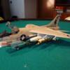
The Freedom Models F-20A Tigershark in Prototype 2 scheme is now complete! This was a fun kit to build. Instructions have some minor issues but not bad. Also am using a different camera so the completed photos represent the color much better and the photos look better. You can see all the completed photos in my blog gallery: https://davidsscalemodels.com/gallery/1-48-f-20a-tigershark/
-
Continuing the work on the Freedom Models 1/48 scale F-20A Tigershark. Fuselage assembled, painted, and decals applied. Working on the missiles and the canopy details now. Getting close to completion. All the build photos are on my blog at https://davidsscalemodels.com/build-log/1-48-f-20a-tigershark/
-
Continuing work on the 1/48 Freedom Models F-20A. Cockpit installed, exhaust installed, and now assembling the fuselage. The fit of the parts is very good. Just had a small section on the spine that needed a little putty. Also added a little weight to the nose to keep it from being tail heavy. More photos at https://davidsscalemodels.com/build-log/1-48-f-20a-tigershark/
-
This is the Freedom Models 1/48 scale F-20A Tigershark. Built by Northrop (before they became Northrop Grumman). I started on the cockpit. The dash board was painted to match photos of the actual aircraft. To create the realistic multi-function displays I painted them a chrome silver and use Tamiya clear green on top. The screens look like real displays as the light reflects light from different angles. You can see more photos on my blog at: https://davidsscalemodels.com/build-log/1-48-f-20a-tigershark/
-
It is now completed! This is the Glenco 1/48 scale J2F-2 Grumman Duck representing VMF-2 that patrolled the Caribbean Ocean off the Virgin Islands. The Duck’s were used for patrolling areas and performing search and rescue of downed pilots. More photos can be seen in the Gallery page on my blog: https://davidsscalemodels.com/gallery/1-48-j2f-2-grumman-duck/
-
The fuselage and wings now have their base coat paint on and the rigging of the wings is done. Still have decals, detail painting, and weathering. I also bought the Squadron Vacu-Form canopy as the kit canopy is very thick and it appears the mold was not clean. Looks like some dirt got into the plastic. More photos in the build log https://davidsscalemodels.com/build-log/1-48-j2f-duck/
-
Work continues on the J2F Duck. The fuselage is now together and the many gaps have been filled. I used clear acetate for the side windows as the kit windows were thicker that the fuselage plastic and obstructed the view inside. I added the duct just under the nose that was in the reference photos. The engine was completed and working on getting the wings assembled and cleaned up. All the build photos can be seen at: https://davidsscalemodels.com/build-log/1-48-j2f-duck/
-
I spent last evening scratch building the dash for the J2F Duck. While doing it I took photos to add a brief tutorial on my blog. The dash looks great. I am getting closer to putting the fuselage together. I need to do some minor modifications to the fuselage then some assembly and filling. The tutorial is at https://davidsscalemodels.com/tips-and-tricks/making-a-cockpit-dash-from-scratch/ All the build photos are at https://davidsscalemodels.com/build-log/1-48-j2f-duck/ The photo below shows the original kit dash on the left, then the photo of the actual dash resized, then the decal and on the right is the final dash. Here is the photo of it installed.
-
Cold and cloudy with scattered rain means I was able to spend the afternoon adding more details to the J2F. Made the rear gun mount, found better wheels in my stash box, and added details to the interior. Need to make the dash for the pilot next.
-
The work continues on the interior of the J2F duck. The interior and landing gear are basically installed. Have many more details to add. I drilled out the exhaust pipes to look more realistic. I did watch “Murphy’s War” last night while working on it. Grabbed some screen shots for details of the engine area. Many scenes of the engine without the cowl provided some nice references. All the build photos can be seen at https://davidsscalemodels.com/build-log/1-48-j2f-duck/
-
Starting on the Glenco 1/48 scale J2F Duck. This is an older kit and does not have the level of details that newer kits have. The Duck is a Grumman built amphibious aircraft that was primarily used for search and rescue. It is unique from other single engine float planes in that the main float and fuselage are designed together. This allows room for more crew members. The scheme that I will be doing is the Marine version that was stationed in the Virgin Islands. All of the interior details will be scratch built using styrene stock and remnants of many photo etch extras I have. I located some build photos from Grumman use as a guide for the interior. I started with getting the cockpit area roughed in. The cockpit floor and the rear bulkhead will serve as my reference point. Working on the Radio/Gunner position at the rear of the cockpit now. More photos in my build log at https://davidsscalemodels.com/build-log/1-48-j2f-duck/
-
The Academy 1/48 F-4B is finished. Overall this kit is great. Very good fit and excellent decals. The instructions could use a little better clarity when it comes to missiles and bombs. So I now have four decades of VF-111 aircraft. All build and completed photos are at https://davidsscalemodels.com/2018/05/16/f-4b-phantom-from-vf-111-completed/
-
The decals are done. The decals are excellent, they conformed to the surface details very well. Next up is the weathering and canopy details. So far this has been a very nice kit to build. I have had no fit issues and everything coming together nicely. You can see all the build photo's at https://davidsscalemodels.com/build-log/1-48-academy-f-4b-vf-111/
-
The base coat painting is done. I also painted the missiles and drop tanks. I used black, brown, and blue pastel chalk to weather the exhaust. They came out very similar to the reference photo's I am using. Should be starting the numerous decals tomorrow. More photo's on my blog under the build logs page.
-
Working on the undercarriage. Landing gear almost complete. The decal for the nose gear door went on very nicely. Looking more like a phantom now with the fuselage done. Getting ready to paint the basecoat then decals. You can see more photo's at https://davidsscalemodels.com/build-log/1-48-academy-f-4b-vf-111/
-
Working on the fuselage. I have the intake ducts, resin exhaust, and cockpit installed and the rear of the fuselage together. More photo's at https://davidsscalemodels.com/build-log/1-48-academy-f-4b-vf-111/
-
One seat completed. It takes some time to build. Add details, paint add more details. You can see and follow the build on my blog at https://davidsscalemodels.com/build-log/1-48-academy-f-4b-vf-111/