


Wolfman63
-
Posts
515 -
Joined
-
Last visited
-
Days Won
88
Content Type
Profiles
Forums
Events
Posts posted by Wolfman63
-
-
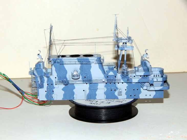
The “Gail Ann” is now completed! The final week started off with adding the decals. The aircraft was then weathered slightly with pastel chalk and then sealed with a matte finish. The HUD was then modified by cutting off the thick gun sight and replacing it with a piece of clear acetate. With the sight installed the armored glass for was then added to the windscreen. I assembled the correct propeller, painted, decals added, and installed it. The wingtip lights were installed and the recognition lights under the starboard wing were finished off. EZ-Line was used to add the antenna. The gun barrels were painted with steel. The last detail I did was to cut off the rear navigation light and replace it with a clear lens. This completed the aircraft!
The end of the week I assembled the display case. I used the Scene-A-Rama “sand” sheet for the base. Once it was glued down I sprayed some dark sand to represent the edge of the taxi lane and some black staining on the areas around the aircraft that were high traffic as well as the supercharger exhaust area. I cut out an area for the nickel nameplate. I used nickel instead of brass for this so the nameplate would stand out a little better. I then drilled holes in the bottom of the aircraft wheels and installed metal pins in order to mount the aircraft in the display case.
With the base finished off all that was left to do was add the clear cover completing this project.
This will be packed up and shipped out the client this weekend. Thank you all for following along on this historic build of the Gail Ann as she was on Saipan in 1944.
Check out all the photos and details from start to finish in my build log at https://davidsscalemodels.com/build-log/1-48-p-47d-razorback-gail-ann/

-
 2
2
-
-
Welcome to week two on the Gail Ann. Starting off with this week’s work, I finished detailing the main landing gear by adding photo etch lines. The tail wheel was installed and the photo etch replacement gear doors were installed. I then spent an evening making the Gail Ann specific decals. On a few of the reference photos it shows the main gear had hub caps. These had a design on them. After some research I found out they were red, white, and blue. I duplicated the pattern and scaled them for the main gear hubs. I also made all the other decals as well. I just need to verify the “Gail Ann” matches the rest of the blue on the aircraft. Since the blue on the aircraft is glossy I coated them with a coat of Vallejo matte finish. This is because the flat tends to change the hue of the color and I needed the slight shift so I can color match the nose decals. I also purchased some resin drop tanks. The drop tanks in the kit were typical of European Theater but the Pacific theater they typically used a 75-gallon vertical seam style drop tank.
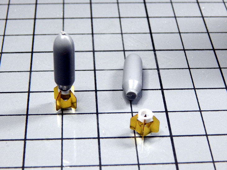
I then started working on the bombs. The fins on the kit bomb are too thick and small for the bomb and the photo etch set includes fins. Once they were bent into shape and the kit ones cut off I learned that the back of the bomb is too small for the fins. I used some styrene tubing and made a sleeve for the fins. Once assembled the bomb now looks like the reference photos.
I started painting all the base coats of neutral gray underside with olive drab, NMF, and blue on the aircraft. For this next week I will be adding the decals then working on the canopy. If all goes well, I may have this completed by next weekend.
Check out more photos and details in my build log at https://davidsscalemodels.com/build-log/1-48-p-47d-razorback-gail-ann/
-
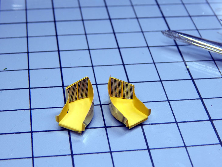
This week I spent time assembling and detailing the engine, assembling the fuselage and wings and started assembling and detailing the landing gear. Starting on the engine the first thing I noticed was the molded pushrods for the cylinders. Using a hobby knife I cut out the pushrods. I then used 30 AWG black wire and cut pieces the length of the pushrods and installed them with the photo etch wire looms. The cylinders were painted using Vallejo’s metal series dark aluminum with aluminum on the valve covers. With the cylinders assembled together I added the photo etch wiring and routed them to the front and rear of the cylinders. The front part of the engine was then painted gray with silver bolt heads. The engine logo and engine ID plate decals are from the Thunder Cals Thunderbolt Insignia and Data Decal set (#48005). I then painted the cowl and installed the engine assembly.
Moving onto the fuselage and wings I used photo etch details on the main gear bays and fuselage duct covers. The nose assembly was mounted to fuselage and the horizontal stabilizers. The overall scheme for this squadron is olive drab overall but the cowl, tail and horizontal stabilizers are near metal finish (NMF) with blue highlights. I sprayed all the NMF areas with Testors bare metal and the blue highlights I am using Model Master True Blue. The wings were then assembled and attached to the fuselage. The Aber gun barrels were then installed. The brass barrels have a lip on one end so they need to be installed from the back side. The assembly is installed and the barrels are pushed in until they hit the stops inside the wing. The bomb racks were detailed and installed under the wings. The main gear struts required a little putty due to ejection marks and the holes for the control arms were filled as these were replaced with photo etch parts. The struts were painted with Vallejo metal series Duraluminum which gives the struts a slightly dirty appearance. For the wheels I am using the hub covered version. I need to finish installing the landing gear and doors and am currently working on the “Gail Ann” specific decals that I need to make.
Check out more photos and details in my build log at https://davidsscalemodels.com/build-log/1-48-p-47d-razorback-gail-ann/
-
The next build is the 1/48 Tamiya P-478D Razorback. This is another commission build. The scheme will be replicating the “Gail Ann” of the 381th Fighter Group, 19th Fighter Squadron at Isley Field, Saipan.For this build I will be using Eduard’s photo etch detail set and Master Model brass gun barrels. The decals will need to be custom made for the specific aircraft. Starting with the cockpit I used photo etch accessories for the pedals, cockpit floor, instrument panel and the side walls. The cockpit was painted Vallejo US Interior green and then all the equipment and switches were painted. The floor and walls were slightly weathered and then the cockpit was assembled. One of the other additions that the photo etch set provides are the ducts for the side vents. The kit just leaves it open to the fuselage. The duct work were bent and fitted inside each side of the fuselage. The yellow chromate was then painted for the inside of the ducts and the inside of the tail wheel bay. I was able to install the fuselage and am now getting ready to build and detail the engine.
Check out more photos and details in my build log at https://davidsscalemodels.com/build-log/1-48-p-47d-razorback-gail-ann/
-
1
-
-
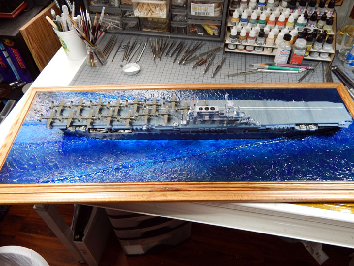
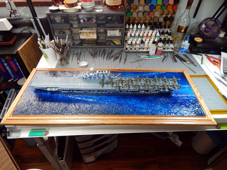
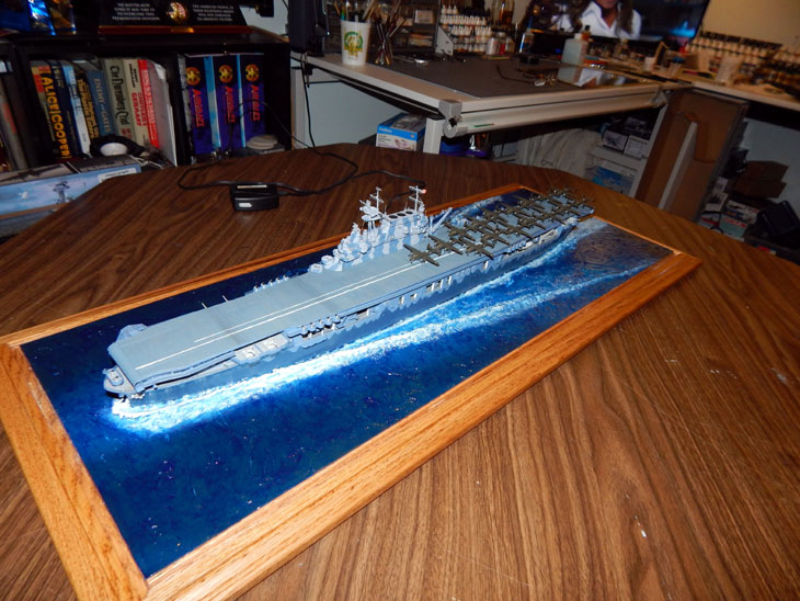
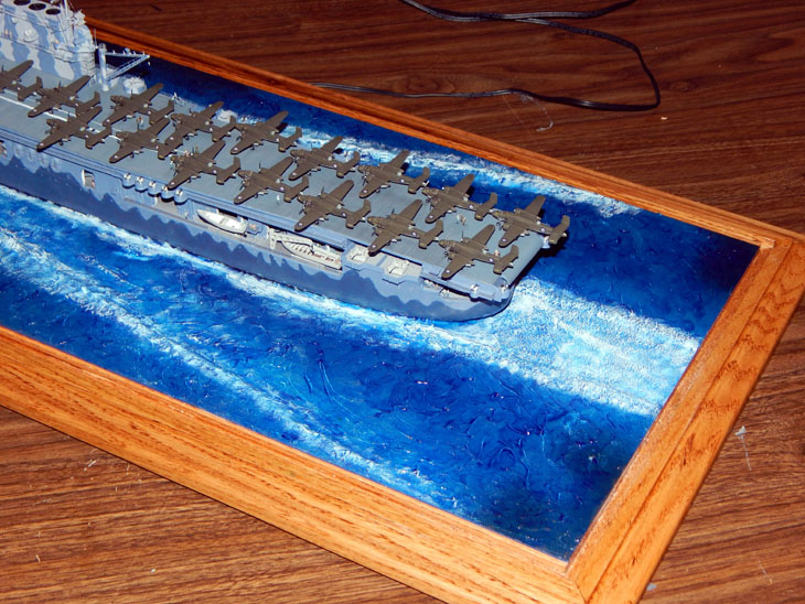
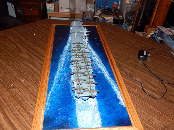
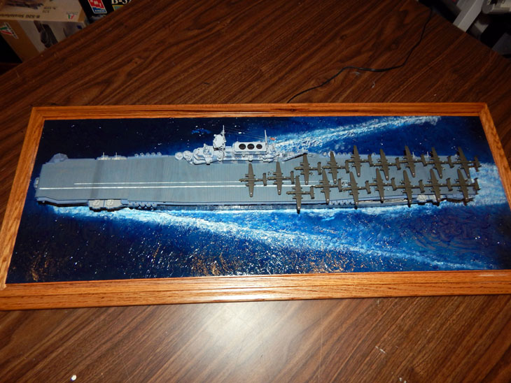
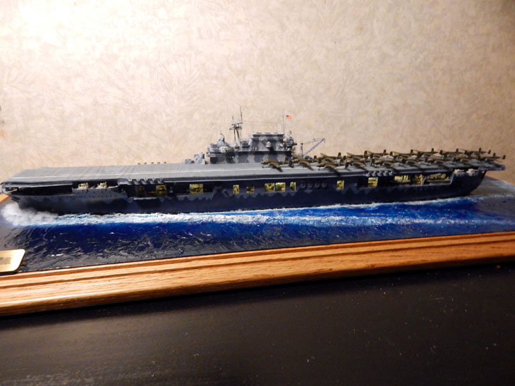
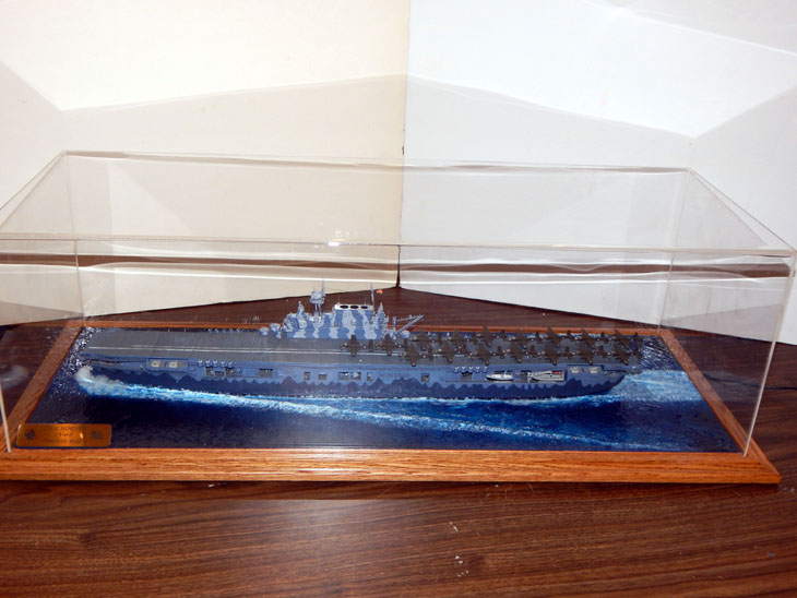
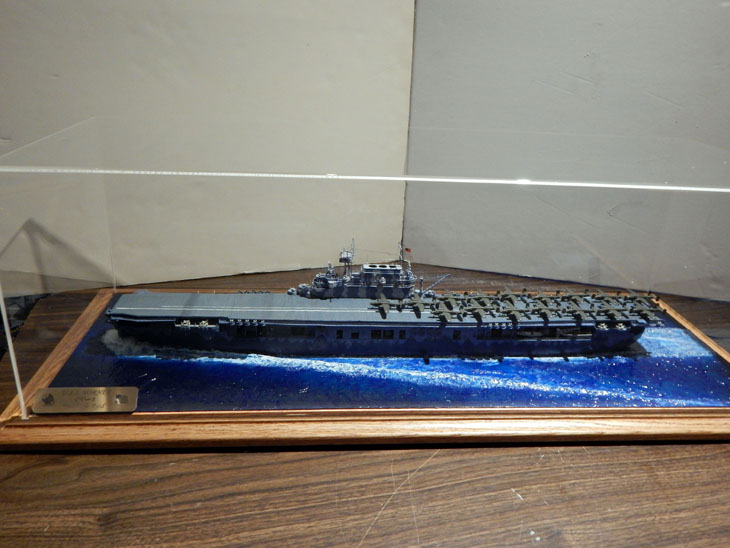
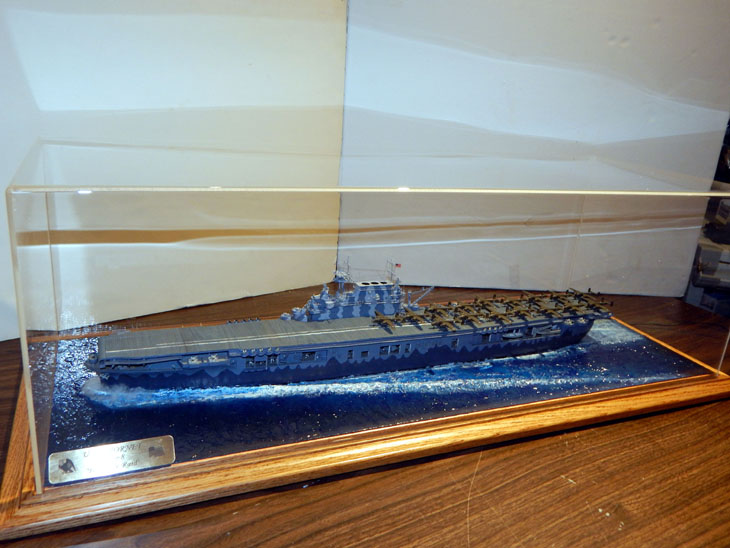
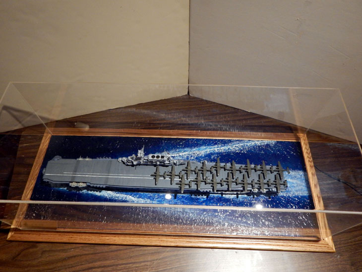
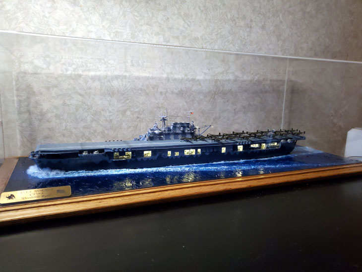
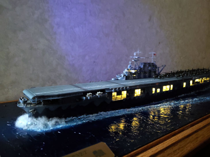
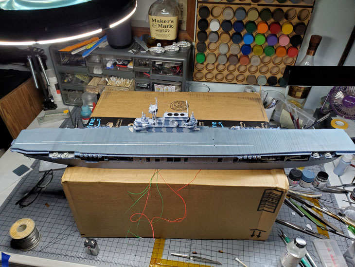
Welcome to last and final week of the Trumpeter 1/350 USS Hornet CV-8 Project!
This is going to be a huge update. I am breaking in up into 3 sections due to the details and number of photos. The first section is adding the figures and aircraft to complete the ship. The second section will be on making the “At Sea” base. The last section is the photos of the completed project. At the bottom is a list of all the accessories that were used to create this project.
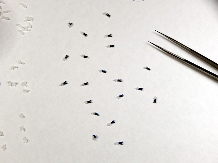
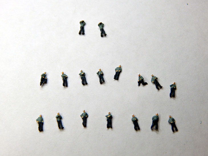
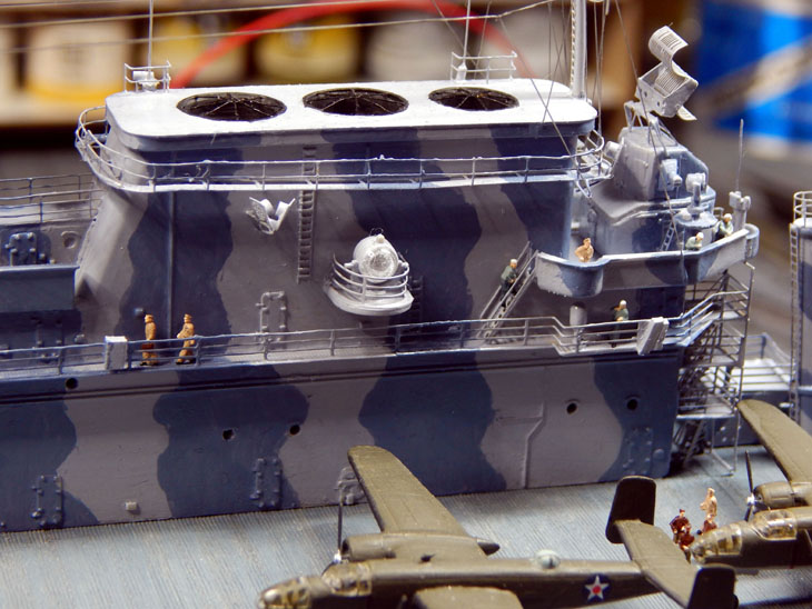
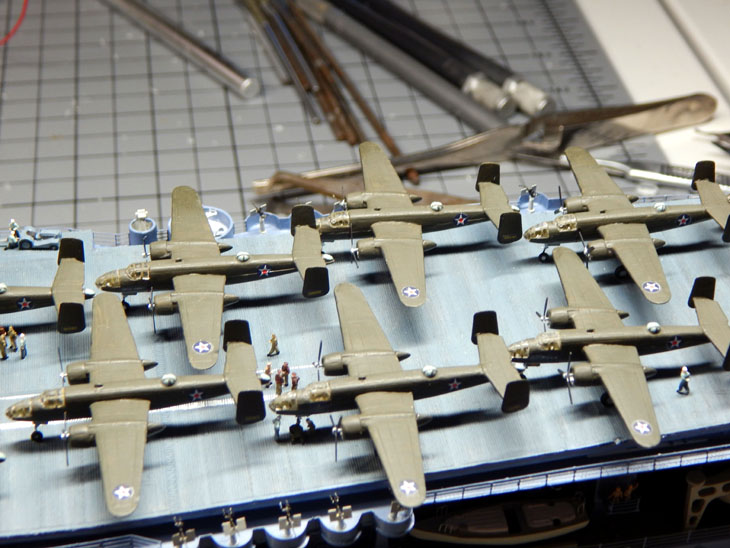
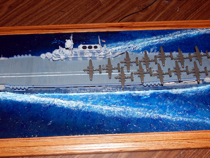
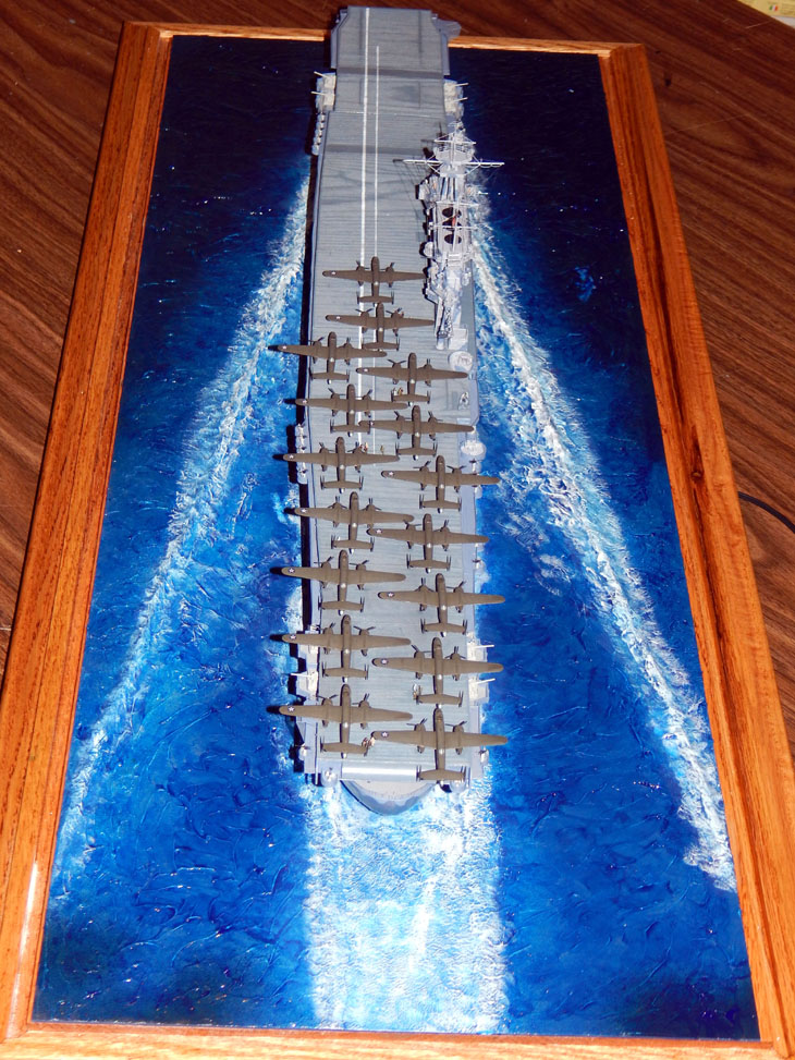
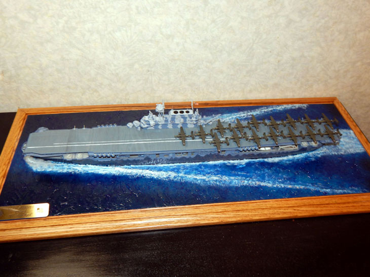
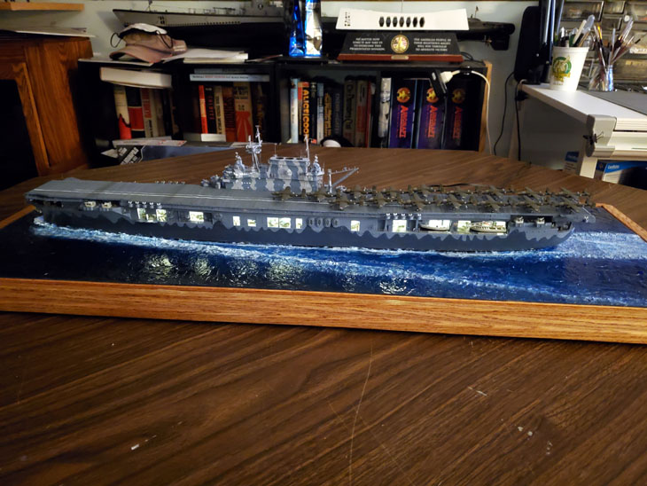
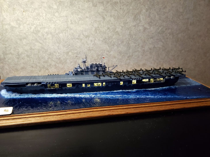
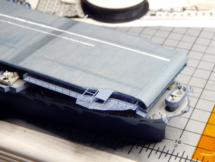
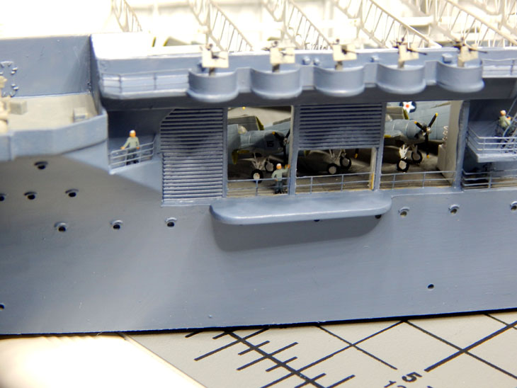
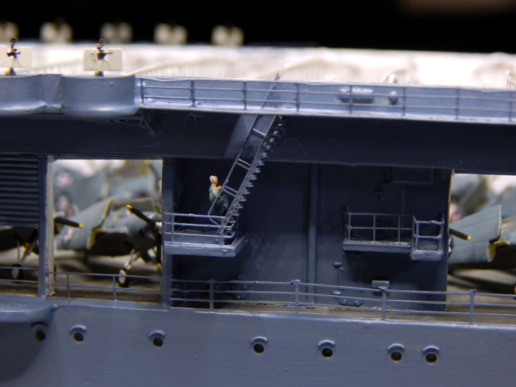
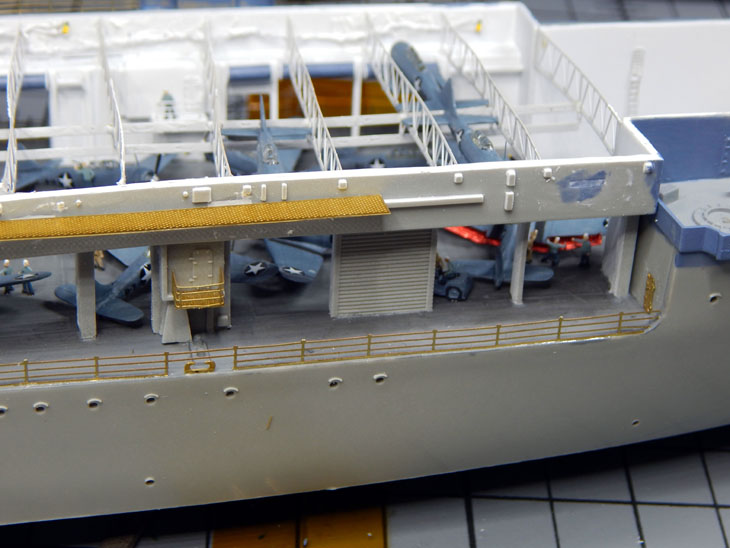
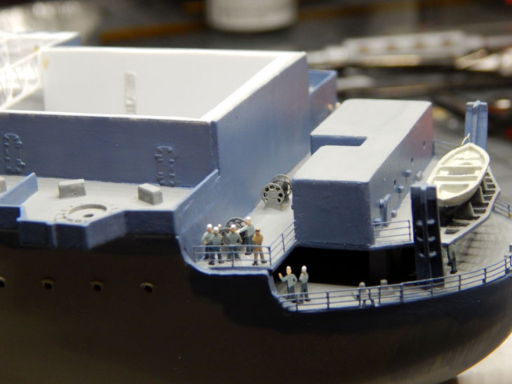
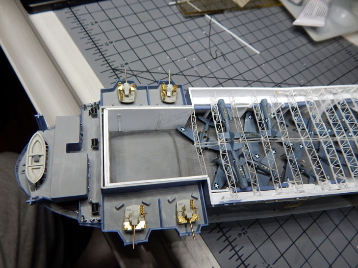
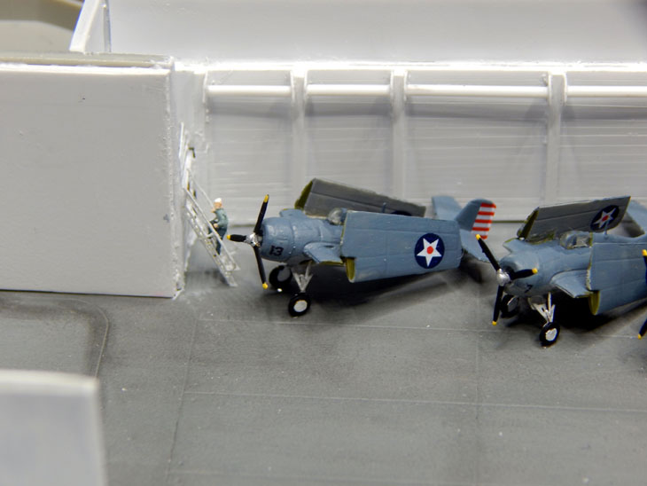
Section 1 – The crew and aircraft loaded aboard. All of the figures used on the flight deck and island are the 3-D printed figures. I separated them into four groups. The four groups are Enlisted Navy, Navy Officers, USAAF enlisted, and the brave USAAF pilots of the Doolittle Raiders. I also added a Moto-tug with a tow bar. The figures come in various poses. It even gave me to sailors using binoculars as lookouts. These were placed on the front of the island at the level just above the bridge. There are two crew members removing the tow bar for storage as well as the USAAF pilots talking on the flight deck. The aircraft were then staged on the deck in their launch order. Doolittle’s aircraft leads the group. I staged them as they were when they were leaving San Francisco Bay. I picked this particular point in time as it was the last time the hangar deck doors would have been open. Once the ship was out to sea the hangar doors would be closed.
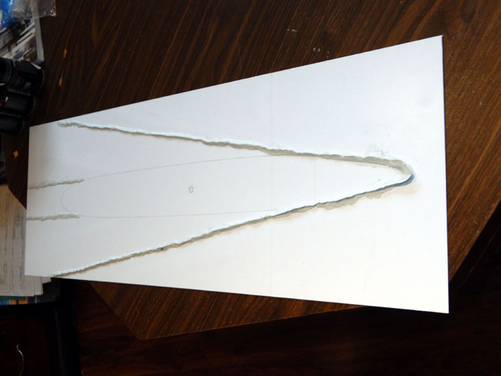
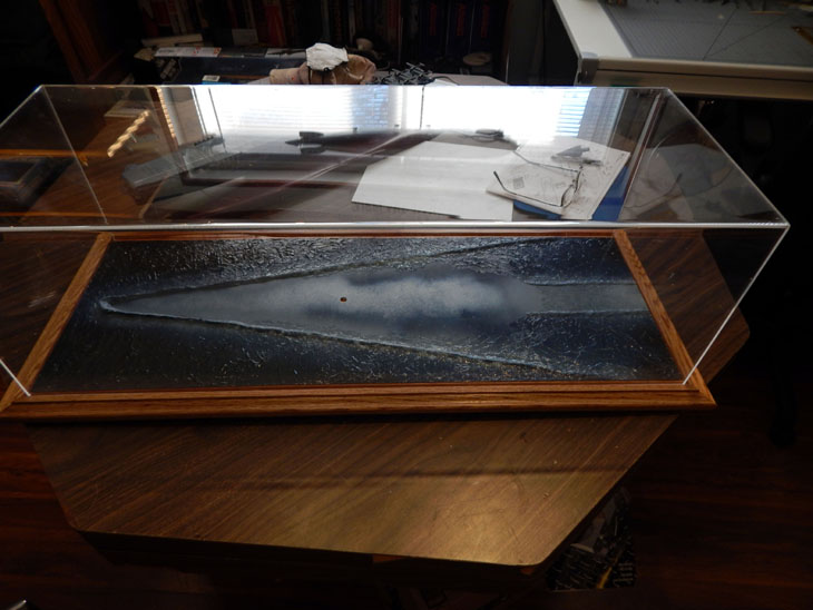
Section 2 – Creating the base. I used two sheets of 1/8” sheet styrene. The sheets are 24” long and 12” wide. After gluing the sheets end to end I trimmed it back to 33” long. Side note: I gave these measurements to Ron and Grandpa’s Cabinets so that the case would hold the base inside the acrylic cove. As usual, Ron’s artistry in making quality display cases was right on. The base fit perfectly inside the cover.
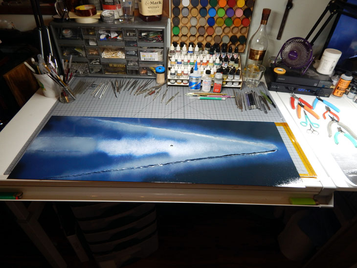
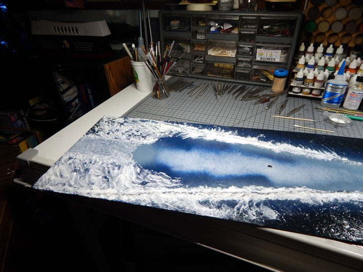
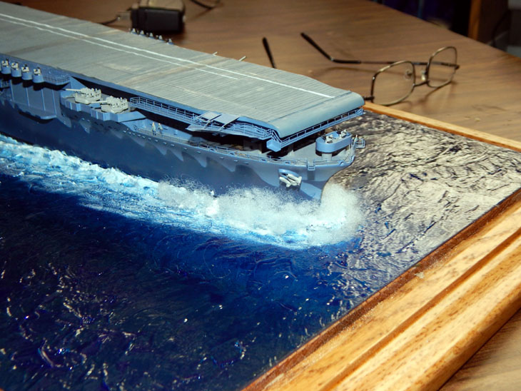
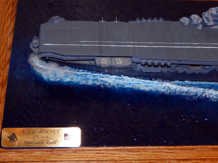
Moving forward, I mixed up some milliput putty to create the bow wake as well as the trailing wake. I then sprayed the base colors. I use dark sea blue on the open areas, regular blue closer to the ship, and intermediate blue for the wakes. I began laying the first coat of acrylic gel. I used a round brush typically used for applying eye makeup. When applying the acrylic gel it is best to make the strokes horizontal to the ship. This gives the waves an even direction. For the trailing wake I dabbed the acrylic gel vertically. The ship model was the glued to the base. The second coat of acrylic gel was then laid down. This coat was to build up the bow wake as well as the splashing along the hull. I also did some vertical dabbing around the bow to give the surface the splashed look from the bow. The third and final coat of acrylic gel was mostly the aft wake to build up the sides even with the hull. After the acrylic gel was fully cured the surface was then painted using Tamiya X-23 clear blue gloss. This gives the “water” a Pacific blue tone as well as blending the three shades of blue. Once dry, I then used Tamiya XF-2 flat white to paint the top of the wakes. The white was then dry brushed on surrounding wave detail near the wake. White was finally dry brushed vertically on the bow spray and the aft wake. Then using the same large brush I used to apply the acrylic gel I dipped it in thinner and lightly brushed all the white areas. This blended the white and clear blue giving various shades of blue and white for the visual effect of the wakes. Finally, once everything was dry I used Pledge Floor coating over all the water to give it a super high gloss (wet look). I then applied a second coat along the bow and used fiber fill (like what is used in stuffed animals or throw pillows) to create the bow splashing the water. I then lightly sprayed some Pledge onto the fibers to add water droplets. This completed the base! Later this coming week I will make a Tips and Tricks page on creating the sea base for anyone who would like to use this method.
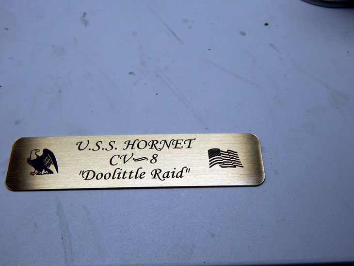
And now the final section – I added a jack under the base so I can plug in the AC/DC adapter to supply power to the LED’s. I then took some sheet styrene and made a mount to hold the brass nameplate. The clear cover was then placed over the ship completing the ship. This project took approximately 30 weeks and 660 hours to build. The kit itself while not quite accurate in the bow section went together very well. The extensive amount of photo etch really brings out the details. Adding the crew figures was a first for me. I prefer the 3-D printed figure more than the Tamiya crew figures. The 3-D figures look way more realistic and have many different poses. The lookouts, The figures that are walking up stairs, and some figures kneeling are just some of the poses that worked out well. The Doolittle Raiders Aircraft decals that I made worked out very well. Once I get the page set up I will be offering these decals in both 1/350 and 1/200 scale. I have also scheduled a photographer to take some professional photos next week. For now below are the final photos I took. I also included a list of all the accessories used on this project and a short video of the completed ship which can be seen in my build log.
I want to thank all my fans and viewers for following along on this long highly detail build. I hope you have enjoyed watching this build. Take Care and happy modeling!
You can see the numerous photos and details from start to finish of the huge project in my build log at https://davidsscalemodels.com/build-log/1-350-uss-hornet-cv-8-doolittle-raid/
-
1
-
-
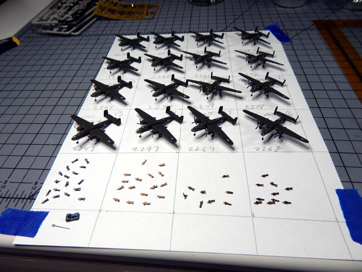
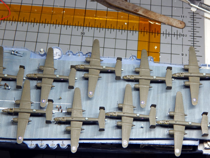
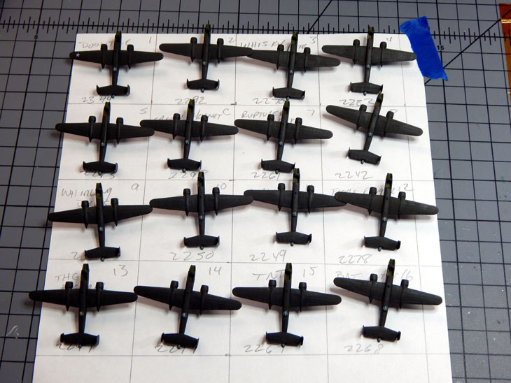
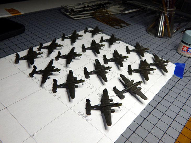
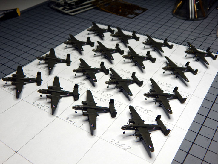
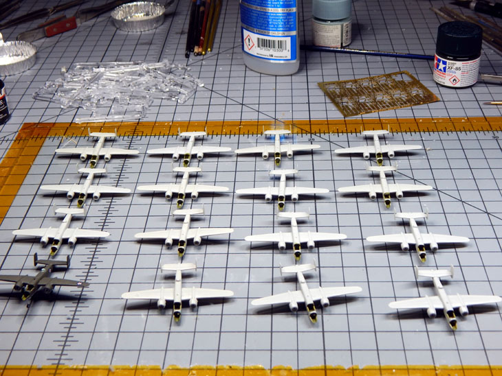
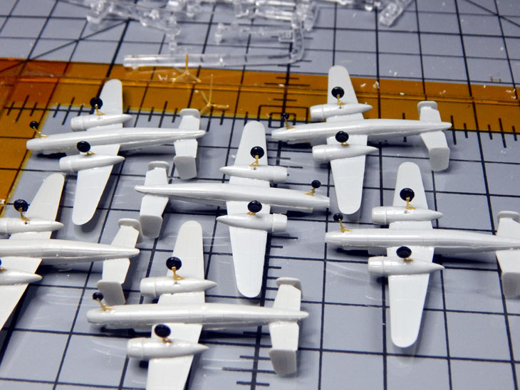
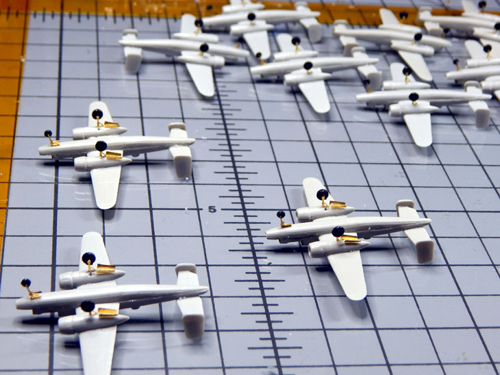
Week 29 – One week closer to completing this project! The B-25B’s are now complete. I spent the early part of the week painting the aircraft, building the propellers and painting them, applying the decals and installing the canopy and nose. They are then set on a grid so I can place them on the ship in order. It was a little time consuming as I had to let the paint dry then the decals set. During these little breaks I started to layout the base. I needed to do this so I can get the exact measurements to order the display case. The case ended up being 33” long, 12” wide and 10” tall to accommodate the base and ship. Once the case sizing was established I contacted Grandpa’s Cabinets ( https://www.grandpascabinets.com/ ) Display Cases for Collectibles - Custom Display Cases and ordered the case. I then figured out the position of the ship and where the wakes will be. Since I am using sheet styrene for the base I decided to use some Milliput to for the wakes. Also during one of these breaks I packed up all the electronics in the hull and glued on the waterline base.
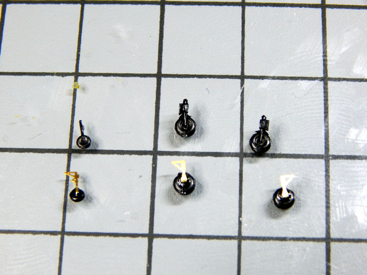
After installing the canopy and nose on the aircraft I then added the propellers and painted the tips. This now completes all sixteen B-25B’s of the Doolittle Raiders. I then grabbed the dish with all the 3-D printed crew and sorted them out (Navy enlisted, Navy Officers, USAAF pilots, and USAAF enlisted). I will be painting them and then placing them and the B-25’s on the flight deck. I will then build up the base.
You can see the numerous photos and details from the start of the huge project in my build log at https://davidsscalemodels.com/build-log/1-350-uss-hornet-cv-8-doolittle-raid/
-
6 hours ago, johneaton said:
That will be fun getting those to balance right. Glued to the deck?
They will be glued to the deck.
-
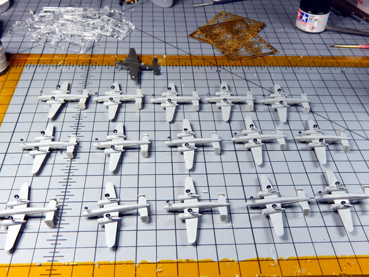
Week 28 - This week has been spent building the B-25B’s. I made an assembly line so I could open up the fuselages for the cockpits. Once all the aircraft fuselages were built I placed them on the flight deck just to see placement. I placed them as they were staged when they pulled out of San Francisco Bay and then how they were staged for the launching just to give you an idea on how much space they had to work with to get perform this mission. I will be staging them as they were on deck as the ship left San Francisco Bay on April 1, 1942.
I then made all the landing gear using the PE struts and the kit wheels which had their struts removed. These were then installed on all the aircraft. Next on the assembly line was adding all the landing gear doors. The undersides of all the aircraft were then painted with Neutral Gray with aluminum for landing gear and wheel hubs. Getting ready to paint the Green Drab on the topside then add all the decals. Then I just need to add the propellers and the canopies. The B-25B’s should all be completed this coming week. I am also going to measure out and start preparing the base for the display case.
You can see the numerous photos and details from the start of the huge project in my build log at https://davidsscalemodels.com/build-log/1-350-uss-hornet-cv-8-doolittle-raid/
-
HAPPY NEW YEAR!!
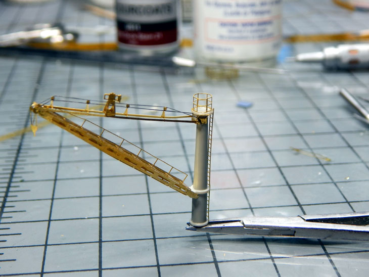
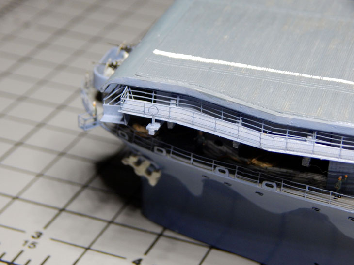
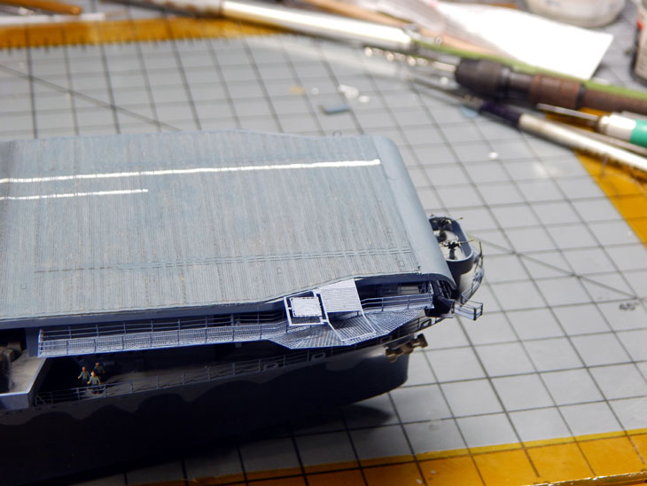
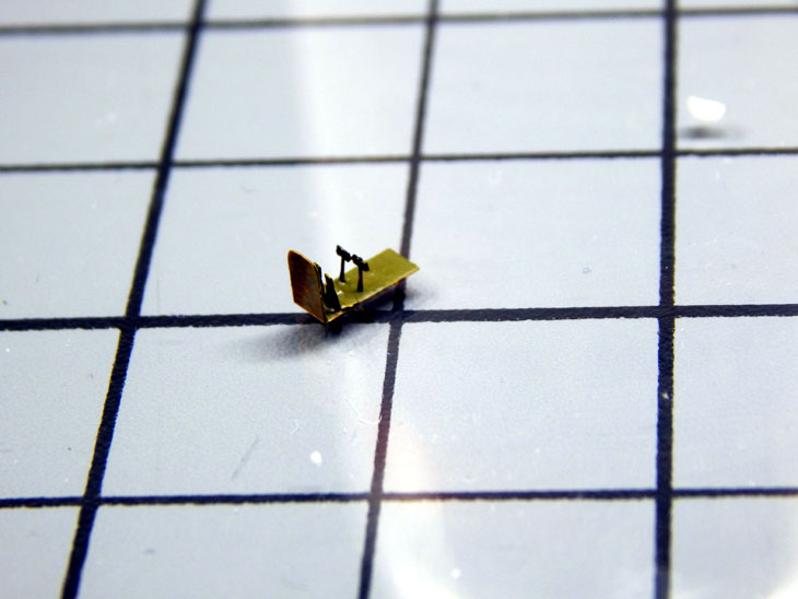
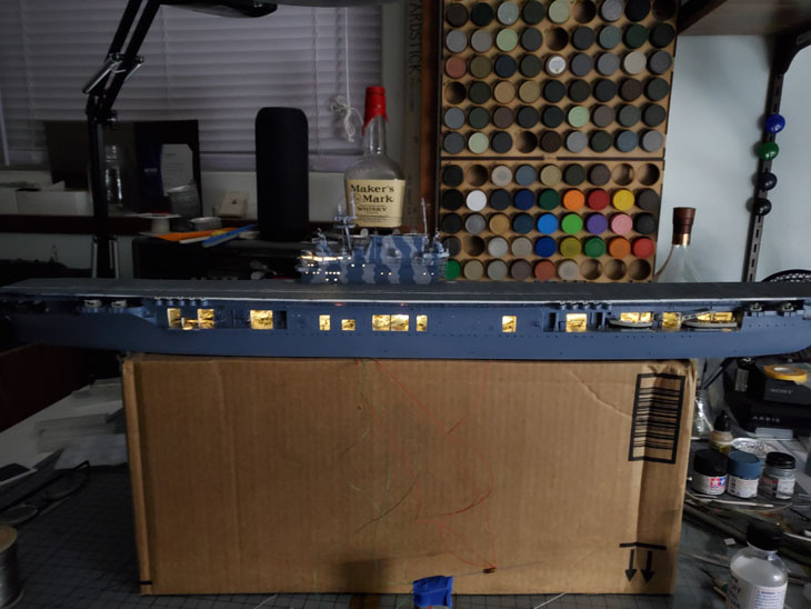
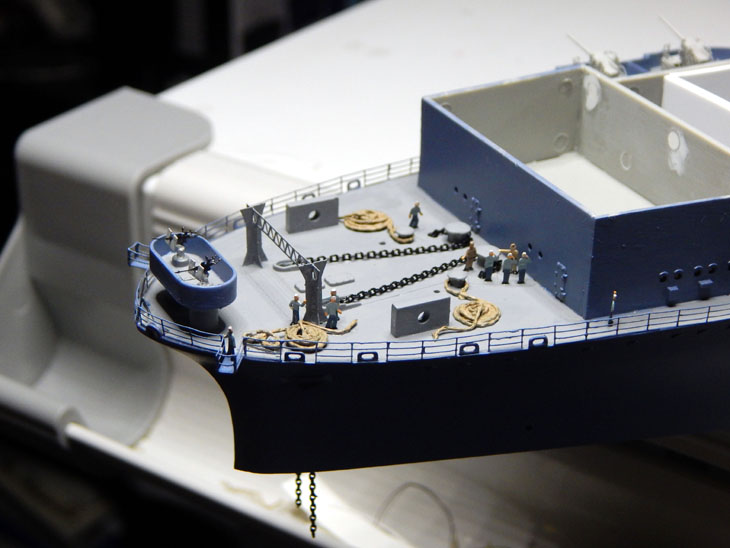
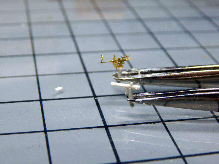
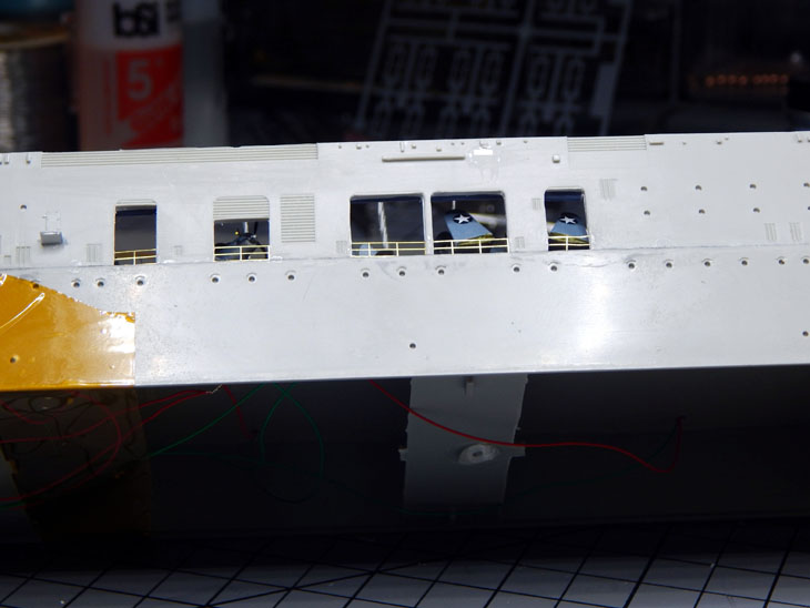
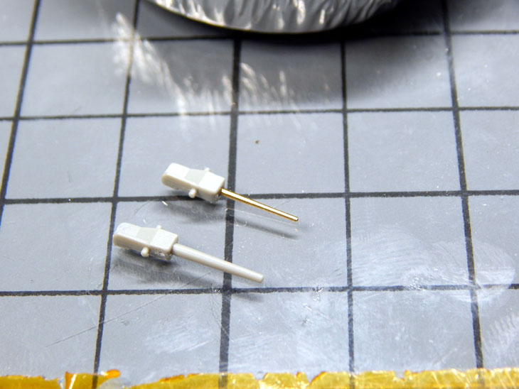
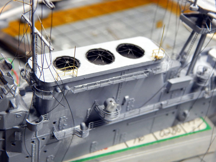
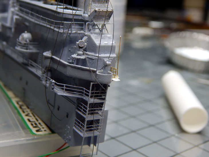
For the first update of 2022 and week 27 of the Hornet Project the ship itself is now complete! I started the week off by adding the guns and final items to the flight deck. On the starboard side where the 20mm’s are next to the island I noticed there is a shield in front of them. I used a strip of styrene to replicate this. I then added the LSO platforms. There are two of them one at the bow and one at the stern. I then used the kit main crane tower and added the photo etch accessories. Using the reference photos I used some EZ-Line fine to rig up the crane cables. The crane was then mounted in the correct location. The kit is slightly off of the actual position.
With the flight deck detailed I then added the remaining details to the hull like the anchors and life rafts. The life rafts have a photo etch webbing as well as the oars and mounting straps. I then added the port loop antenna to the bow and the two starboard antenna mounts. I then added the LSO folding walls in the down position. The two gang planks were added to each side in the folded position. At this point the ship itself is now complete. I then started on the sixteen B-25B Doolittle Raiders. The photo etch set comes with a cockpit. The cockpit consists of the cockpit bucket with two seats, two control sticks, the instrument panel and the bulkhead for nose. The fuselage of the B-25B needs to have the two locating pins and sockets removed in order to accommodate the cockpit. As for the B-25B kit, there are a couple of things that I do not like. First, they have a belly gun turret which needs to be removed as these were not on the Doolittle Raider aircraft. Second, they include the canopy and nose in clear but have the upper turret and tail molded in the gray. These are large enough that they could have included clear parts. Actually, if the upper fuselage was molded in clear it would also help with the tail as well. I ended up painting the turret and tail canopy light blue and then the turret frame in the green drab.
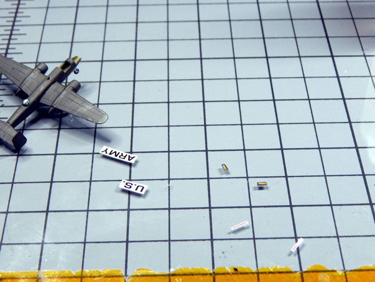
Once the fuselage was assembled and wings added I then used the photo etch for the landing gear and landing gear doors. The instructions have you cut off the kit struts and use the wheels for the photo etch landing gear. I used the same method as I did with the other aircraft for the propellers using 0.5mm fiber optic for the propeller shaft and hub. The kit only comes with some of the tail numbers (not all are the correct numbers) and the insignias. I made my own set of decals for them. These include the correct tail numbers, the prop warning stripe, the U.S. ARMY under the wings and the correct nose art for the few aircraft that had them. The first one painted is Col. Doolittle’s lead aircraft. I have eleven more to build and then paint and place the 3-D printed crew members. Next week I should be starting the “at sea” base. Need to figure out the exact size then contact Grandpa’s Cabinets and order the case.
You can see the numerous photos and details from the start of the huge project in my build log at https://davidsscalemodels.com/build-log/1-350-uss-hornet-cv-8-doolittle-raid/
-
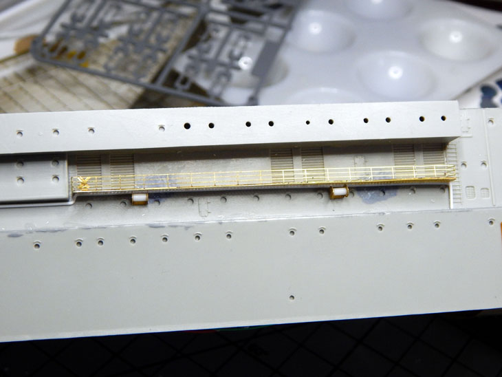
Week 26 on the USS Hornet – I have hit the 6 month mark! First, I want to say I hope everyone had a great holiday. With the holiday season here I have a few days off from my regular job and was able to get a lot of work on the Hornet. To start with I added crew members to the bow and hull. There are a few standing near doorways as well. Once they were placed I moved onto the flight deck catwalks. For the bow end I added the catwalks and rails. They were then painted and mounted to the flight deck. For the aft section there are also four 20mm AA guns as well. I cut off the gun sections from the kit catwalk and trimmed them to fit the photo etch catwalks. I am waiting to add the AA guns until later to avoid accidently damaging them.
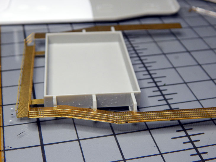
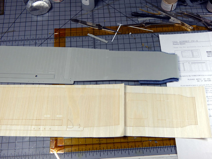
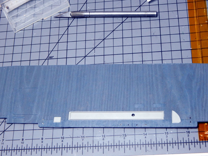
The next part is new for me. I purchased the Nautilus Models wood flight deck. The directions strongly call out to stain/paint the deck prior to installing. They recommend using the White Ensign US11 Flight Deck Stain 21 which is made by ColourCoats. There are sections for the island and other flight deck details that need to be cut out to fit on the deck. The wooden deck is self-adhesive so you just need to use a knife to cut through the backing paper to remove them. The decking was them painted. I next painted the two lines that were used to guide the B-25’s down the deck. The wider line was for the port main gear and the thinner line was for the nose gear. Another interesting marking that was unique was they actually glued sheets of non-skid to the deck at the 450ft mark for the main wheels. The purpose at the time was to stage the B-25 wheels on the spots. This was to line up each aircraft on the exact same starting point for the launch. I replicated these by painting two black squares in the correct locations Once it was dry I did a little weathering with dark gray pastel chalk around the elevators and the landing area.
A hole was drilled into the flight deck where the island goes so that the wires for the island lighting could be routed. The island was then mounted to the flight deck. I routed the wires through the hangar and then to the bottom of the hull. I then checked to make sure all the lighting works. I then needed to adjust the intensity of the lights. They are way too bright. Since the island uses 5mm LED’s and the hangar deck is only PICO size I needed to adjust the intensity for each section. To accomplish this I added a 650 ohm resistor for the power in. This made the hangar deck lighting correct but the island was still too bright. A 470 ohm resistor was added to the wiring going to the island. This corrected the intensity level to a much more realistic level.
Finally, for this week I used a box to raise the model. This was done to allow me to paint the 5-N Navy Blue camouflage on the bottom of the hull. Using a reference photo I duplicated the scheme. I am currently working on adding the rest of the details to the flight deck like the pilot house and the deck crane. There is light at the end of the tunnel! I am hoping to start working on the B-25’s then all the crew members for the flight deck in the next week.
You can see the numerous photos and details from the start of the huge project in my build log at https://davidsscalemodels.com/build-log/1-350-uss-hornet-cv-8-doolittle-raid/
-
1
-
-
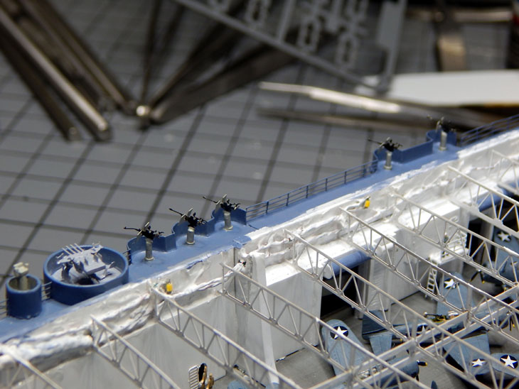
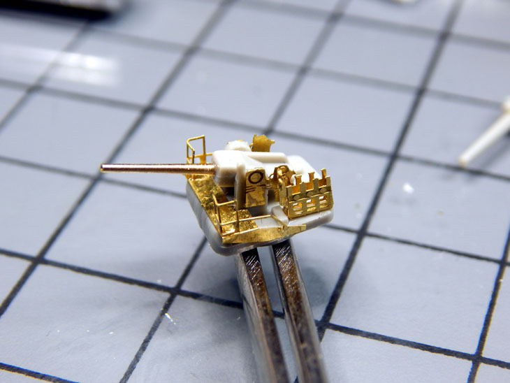
The 25th week covers assembling and installing all the anti-aircraft and 5” guns. The Oerlikon 20 mm cannons took some time to assemble. There are only 4 photo etch parts as well as the kit part modified for the mount. Assembling all 28 of them took three evenings but they are all built, painted and mounted. I then painted the 5” guns and mounted them.
I then added the few remaining ladders for the catwalks. For the one ladder that goes up to the catwalk on the port side I added one of the 3-D printed crew members that are positioned walking up a ladder. Right now I am painting many of the crew that will be positioned around the hull and bow. Once the crew has been placed the hull will be complete and the flight deck assembly can be detailed and installed.
See all the photos and details from the start in my build log at https://davidsscalemodels.com/build-log/1-350-uss-hornet-cv-8-doolittle-raid/
-
1
-
-
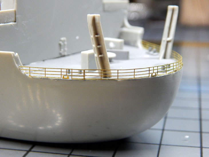
Here we are at week 24 – This week I have all the catwalks installed and all the railings installed. Before I get into the details of the hull I need to make a correction from last week. The AA guns are not .50 cal. The reference book, as well as some online sources, states they used .50 cal for AA on the Hornet. As it turns out the US Navy found the .50 cal was not very effective. So in February before the Hornet sailed out of the shipyard they removed the .50 cal AA guns and replaced them with Oerlikon 20 mm cannons. The photo etch gun I previously built was the ones that came with the detail set and they are the 20mm.
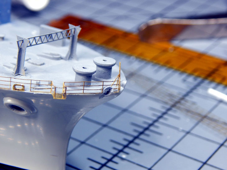
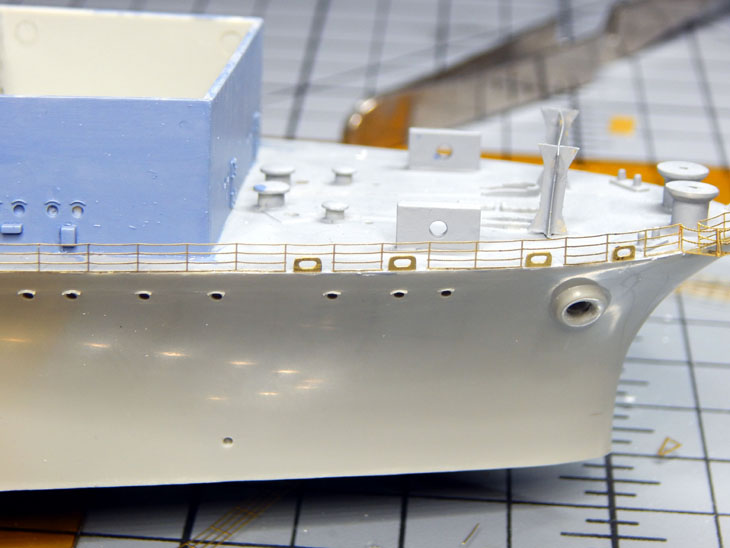
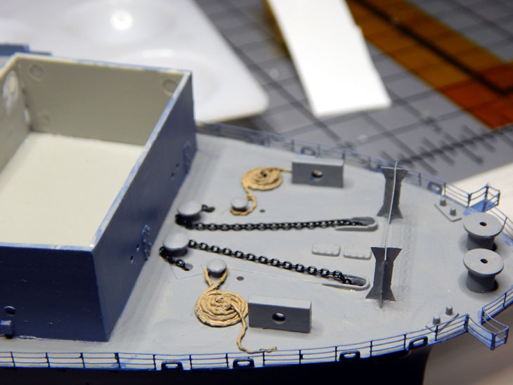
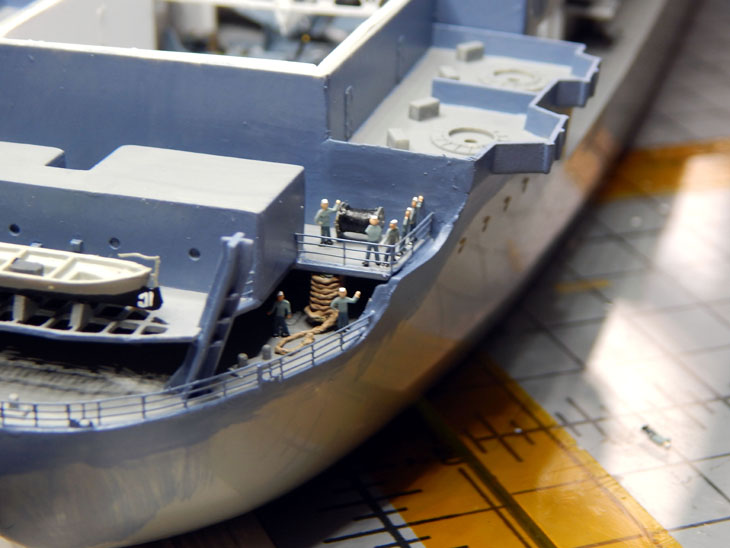
Getting back to the build, while installing the railing on the bow I noticed there is a flag pole on the bow where the Union Jack flag is typically flown. Using some photo etch scraps I made the flag pole. Next I then painted the hull with the Ocean Gray base coat of paint. I then started detailing the bow. In the reference photos they had coils of mooring lines on the bow. I wanted to replicate these. I tried a few different things like regular string and wire. Neither of these looked like coils of rope. I then found a spool of 50lbs braided fishing line that I previously used as aircraft tie down rope for the 1/48 B-25B “Ruptured Duck” Doolittle raider aircraft I built previously. So I tried to coil it up but it was difficult keeping the coil. I then came up with a jig and made the mooring rope coils.
You can see the detailed process I used in my Tips and Tricks section at: https://davidsscalemodels.com/tips-and-tricks/how-to-make-mooring-ropes/
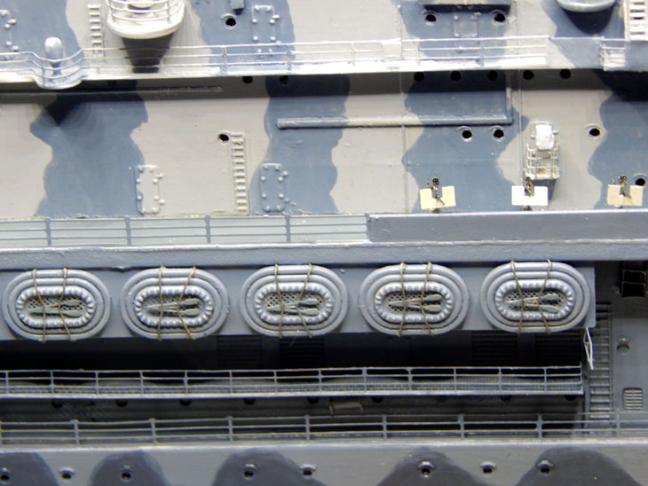
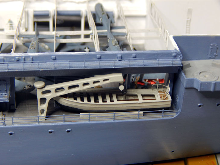
With the mooring ropes installed I then added the anchor chains. There are two launches on each side of the ship. These are the boats used as life boats and captains launch. The kit has the basics for each one but the photo etch set has details like rudders, rails, flooring, and life preservers. Once the boats were painted I looked at the placement. The kit does not provide the cradle used to store the boats on deck. I took some square stock styrene and scratch built the cradles. I then cleaned up the boat cranes on each side and installed them. I am working on the other twenty three 20mm AA guns and then need to add crew members to the bow.
See all the photos and details from the start in my build log at https://davidsscalemodels.com/build-log/1-350-uss-hornet-cv-8-doolittle-raid/
-
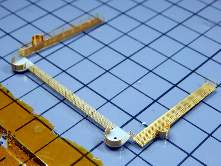
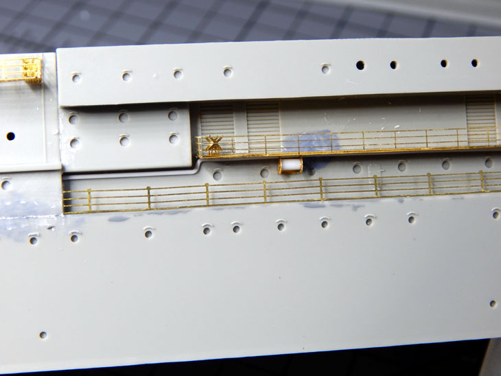
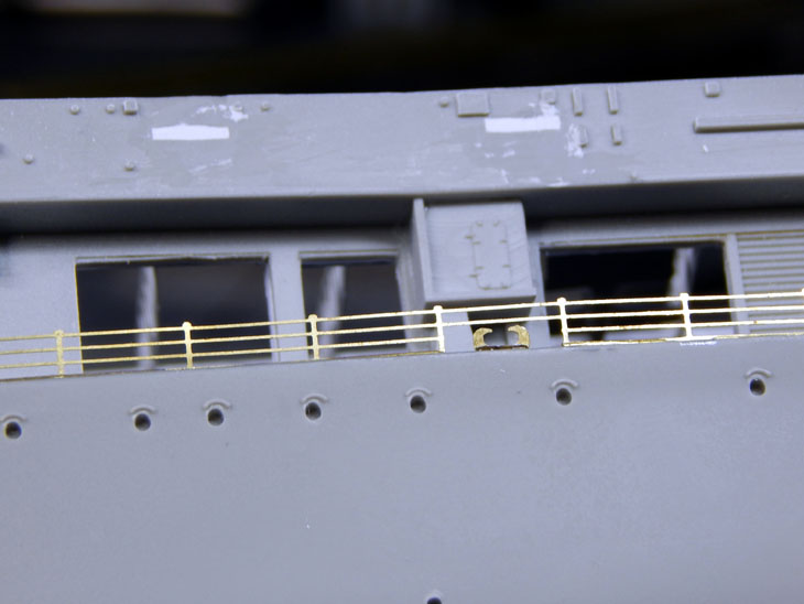
Week 23 has arrived – Continuing with the hull catwalks and railings. The catwalks are a mix of kit and photo etch. The kit sections are where the guns mount. As I mentioned before I removed the kit shields and added the photo etch versions. While on the subject of the guns, I looked over the .50 cal guns. The photo etch version has the thin base. So like all the other guns I went with a mix of kit and photo etch. I used the base of the kit and added just the gun to the base. The photo etch guns also have a few pieces. The shield and the shoulder mounts are separate parts. Once the sights are positioned I added the shield and mounts, the base was then notched to mount the gun.
I then moved on to the catwalks. Another difference from the kit to the photo etch is the catwalks have different levels when they go under the edge of the flight deck. Once I finished the catwalks on the starboard side I added the railings to the smaller levels and the safety rails for the open hangar doors. One thing to note, on the port side I did the railings first. With as delicate as the photo etch catwalks are, I have had to go back and repair some areas. I kept accisently bumping them or touching them incorrectly while working on the lower rails. When I went toe the port side I did the railing first and this works out much better. I need to add the railing to the catwalks then onto building all the .50 cals (20 just at the catwalk level) and then get the base coat of Ocean Gray on the hull. I am estimating the ship to be completed in about 6 more weeks then I need to start working on the “at sea” base and order the display case once I figure out the size I will need.
See all the photos and details from the start in my build log at https://davidsscalemodels.com/build-log/1-350-uss-hornet-cv-8-doolittle-raid/
-
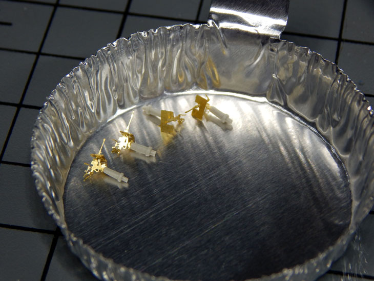
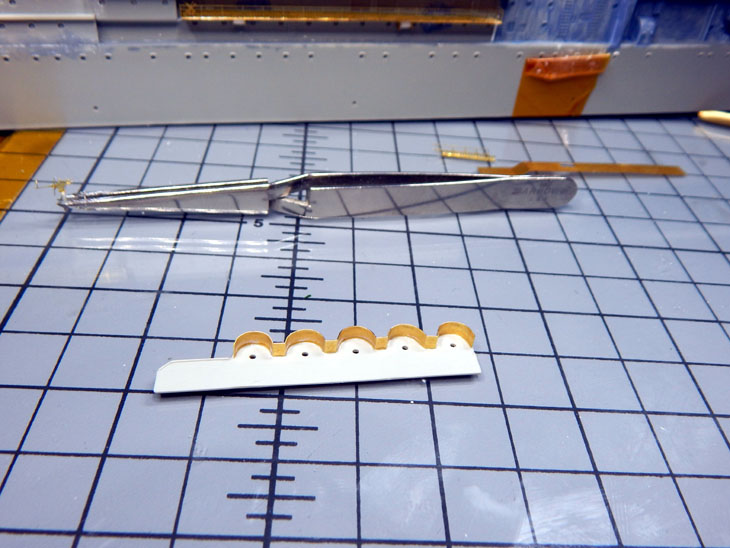
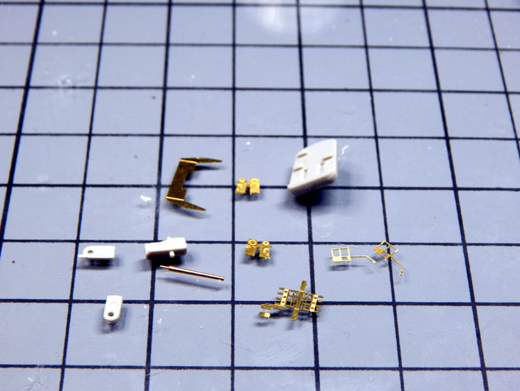
Week 22 – Starting at the stern I added more details. I added some crew members, the fantail launch, and the mooring rope winch on the starboard side. I used some 50lbs test braided fishing line for the mooring rope and coiled it around the winch spool. The kit does not provide an actual spot to hold the launch so I scratch built the cradle that holds the launch. I then started making the eight 5” dual-purpose guns. The kit gun mounts had a couple of issues. First the kit parts lacked detail and the gun barrels were more like 10” barrels. I cut off the barrels and replaced them with Aber brass barrels. I then added the photo etch details to provide a more accurate look.
Moving on I am now working on the catwalks. Since I am doing an “At Sea” display I used the full hull lower section as a placement guide. With the photo etch catwalk set from White Ensign there are sections that are replaced. The kit shields that go around the .50 caliber guns are too short and thick. These are cut off and replaced with photo etch versions. I started on the aft starboard side. I am working may way along the starboard side first. For the midship catwalk I added some empty reels that sit just under the catwalk. There are also small platforms that require railings added as well. Once the catwalks are done I will detail the bow and then begin detailing the underside of the flight deck.
See all the photos and details from the start in my build log at https://davidsscalemodels.com/build-log/1-350-uss-hornet-cv-8-doolittle-raid/
-
1
-
-
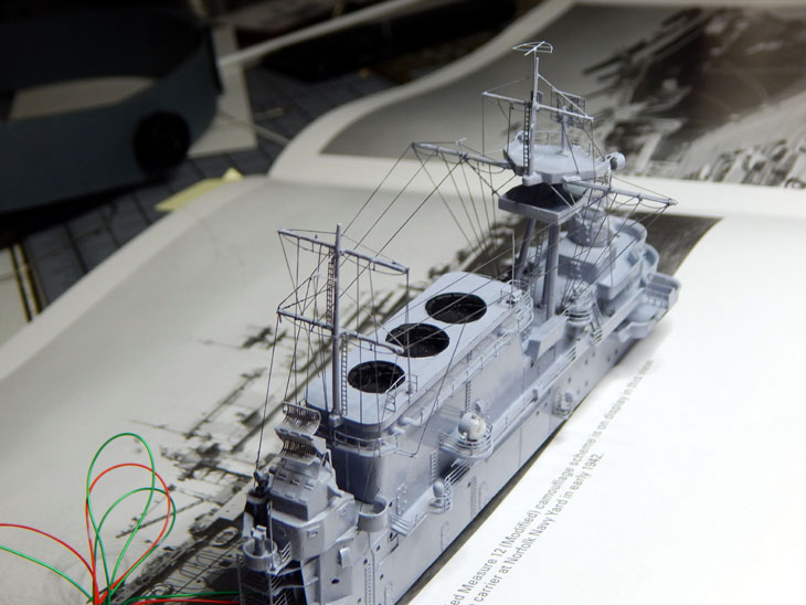
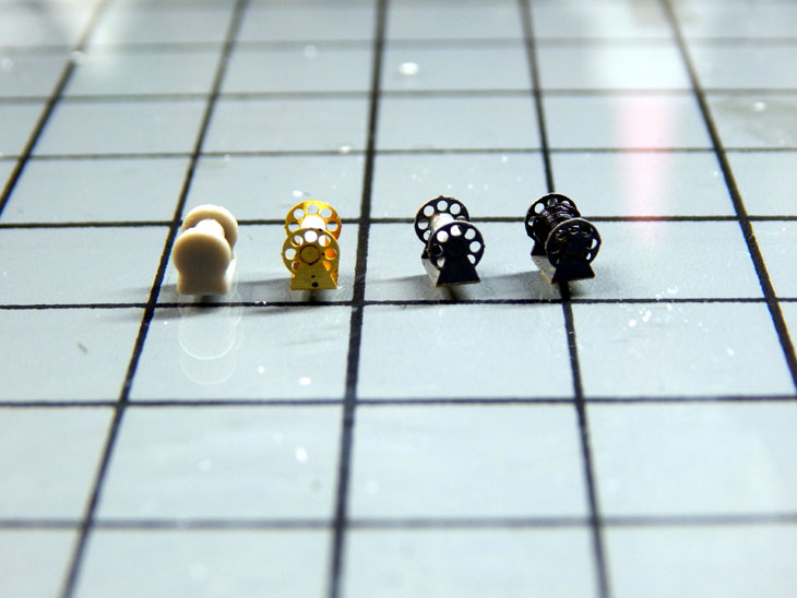
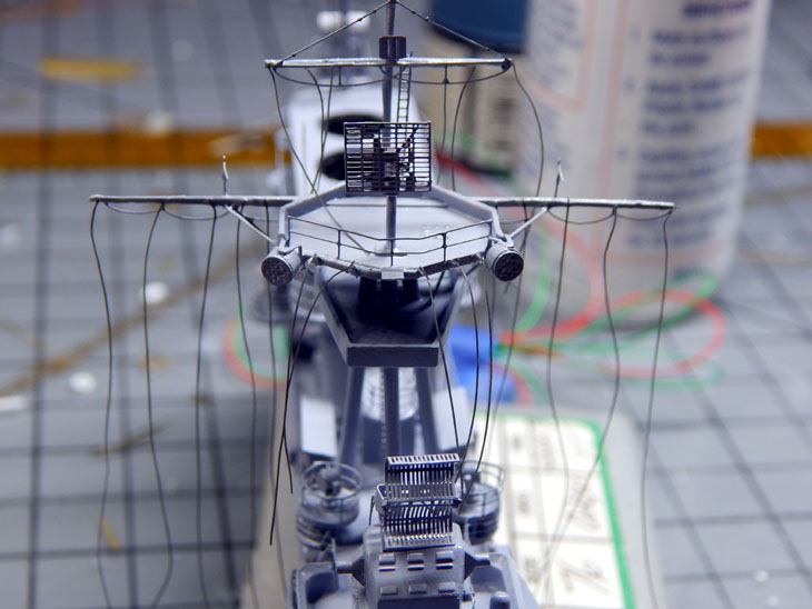
Here we are at week 21 of the USS Hornet “Doolittle Raid” project. This week I was able to complete the island. All 34 lines of the rigging have been mounted. Once the rigging was completed I then painted the camouflage on the island using the photo references in the Hornet book. The pattern that the kit shows and what were actually on the ship differs slightly. The lines have a slight shift when they reach the catwalk half way up the island on the actual ship. I then finished the 4 quad AA guns used on the flight deck. I was looking over the flight deck assembly and decided to detail the hull next. This is being done as the catwalks that go around the hull for the flight deck need to be installed and painted before placing the flight deck on. Since all the catwalks are photo etch I filled all the mounting holes for the kit catwalks with putty. I then started at the stern I added the edge railing and worked on the second deck. This has three hose reels on it. The kit has cutouts for the kit reels. I filled these in with putty and then assembled the photo etch versions of the reels. I used black 6lbs test braided fishing line for the hoses. I used three layers of line on each reel. Need to research the rails and stairs on the stern then onto the catwalks.
See all the photos and details from the start in my build log at https://davidsscalemodels.com/build-log/1-350-uss-hornet-cv-8-doolittle-raid/
-
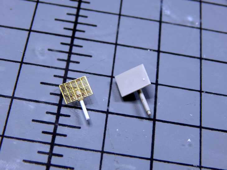
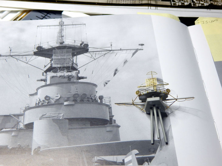
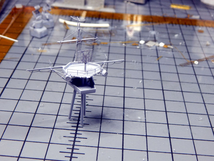
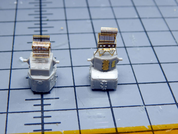
Here we are at the 20th Week of the USS Hornet “Doolittle Raid” project! I am still working on island details. As I was researching all the rigging I found more details that I needed to add to the island. I found out that there are three whip antennas on the island. Two of them are on the funnel cap with rails and one on the aft end of the island. I scratch built these using photo etch and styrene rod for the base. I began attaching the first layer of rigging for the forward mast. I am using EZ-Line black fine for the rigging. With the lines attached on the one end I let the CA glue cure for a while before starting to attach the other end.
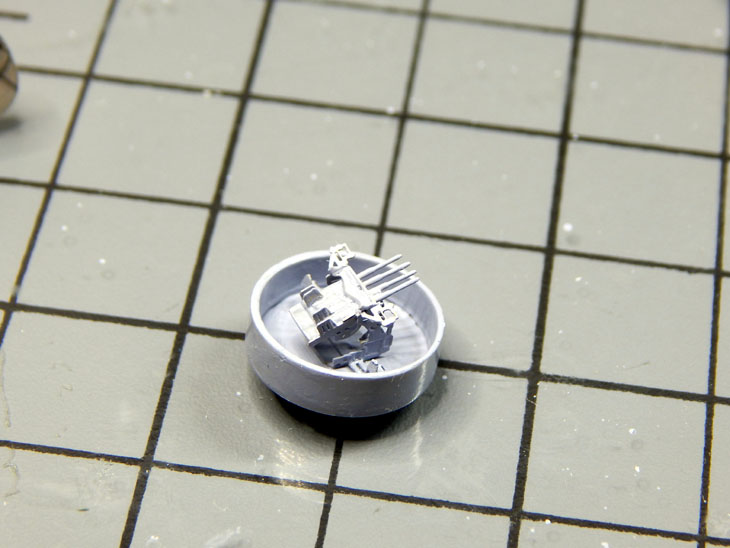
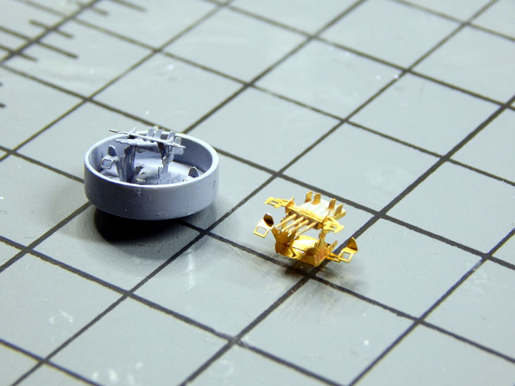
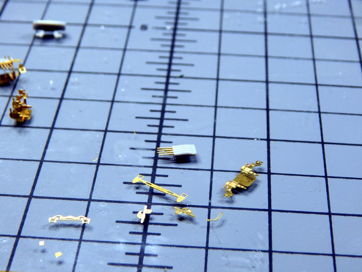
While the rigging was curing I started looking at the quad 1.1” anti-aircraft guns that sit on the flight deck. I assembled the kit version just to see how they look. They are very plain looking and seem too small for the scale. I then built up the photo etch version. They looked better but being photo etch they seemed too thin. I then decided to use a mix of the kit parts, Photo etch parts, and Aber 1/350 1.1” brass barrels for them. Using the “body” of the guns from the kit I installed the brass barrels and then installed the photo etch mount, seats, gun sights, and ammunition feed boxes.
I moved back to the rigging and started with the aft mast. One of the things I needed to add was the mount for the flag. I used some more photo etch scraps to make the mount. I am continuing with the rigging. It looks like there are going to be three sections, the forward main mast, the aft mast, and then the rigging that goes between the masts. All told there are roughly 20 individual lines that need to be added and routed. Once the rigging is finished I will do some touch up with the base color then add the camouflage color and finally the crew that will be placed on the island.
See more photos and details from the start in my build log at https://davidsscalemodels.com/build-log/1-350-uss-hornet-cv-8-doolittle-raid/
-
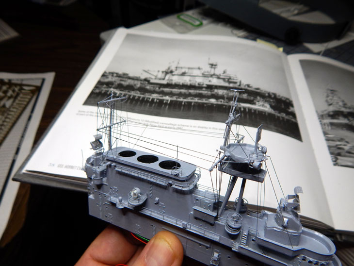
Week 19 – Work was slowed a little this week as I had the laptop I use for making decals started to die and needed to be replaced. I spent a couple of evenings changing over to a new laptop. Turning back to working on the project I added some more details to the island. There are smaller search lights around the island which have been included with the photo etch set. One of the kit search lights on the aft side of the island mounts to the deck. However after review of the photos it is actually mounted on a raised platform. I scratch built the platform and mounted the search light. I also used the photo etch SK antenna rather than the plain looking kit version.
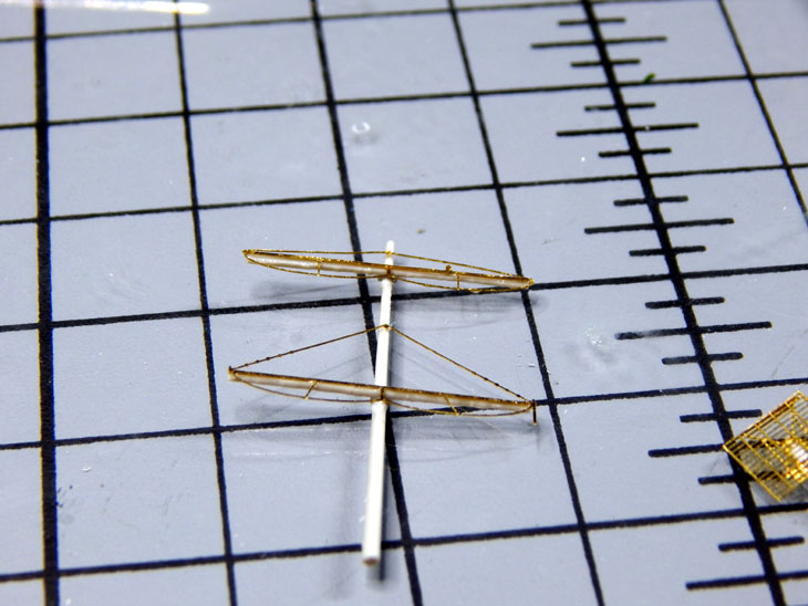
Next I started on the masts. I started by removing the molded ladders and added photo etch details. The aft mast spars were detailed and set aside. The main mast needed a lot more work. Comparing the kit mast and the photo etch parts there were still a lot of details missing. To start with I added the hatch and ladder to go between the two platforms. Next was the top platform in the photos has a small extension on the forward side as well as mounts for rigging. I was able to locate some photo etch pieces in my spares bin to replicate these. Next were two large spot lights. The photo etch set had the face covers. I used a sprue tree the same diameter and then some spare photo etch parts to make the mounts for them. I then started painting the island and main mast.
Speaking of paint, after some research I found out the paint scheme is three colors not two as the kit instructions show. The island is haze grey with ocean grey camouflage. Below the flight deck the hull is ocean grey and navy blue camo. I chose to use the Scale Colors paint for this scheme. I am using SC004 5-H Haze Grey, SC003 5-O Ocean Grey, and SC002 5-N Navy Blue. This is the first time I am using this brand of paint.
I need to finish some details on the aft mast then finish assembling the island to start the tedious task of doing all the rigging.
See more photos and details from the start in my build log at https://davidsscalemodels.com/build-log/1-350-uss-hornet-cv-8-doolittle-raid/
-
1
-
-
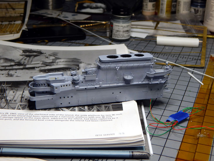
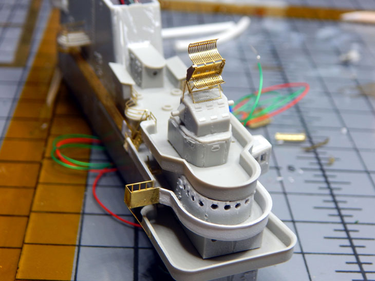
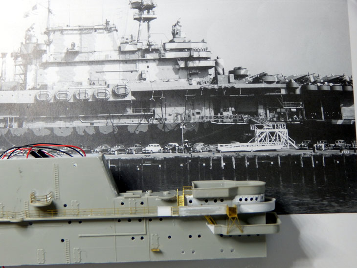
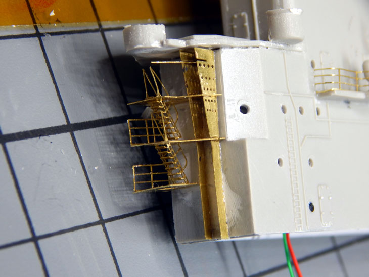
Welcome to week 18 on the Trumpeter 1/350 USS Hornet project. This week was spent detailing the gun directors and the island. On the gun directors I first removed the molded “blocks” that represented the door and hatch. These were replaced with photo etch pieces. I then used the photo etch for the antenna and mount.
Switching over to the island I removed the molded porthole covers form the bridge and replaced them with the photo etch parts. The photo etch parts have the slots in them where the kit ones did not have them. I then started on the starboard side of the island. After reviewing the photos in the reference book I found that the three “portholes” near the top of the island are actually vents. I filled the portholes with putty then used a small styrene tube and cut an angle on them and installed them over the previously filled holes. There are also a couple of ducts and a storage bin mounted to the railing. After digging through my stash of extra photo etch parts I found a few items to scratch build a platform that has a cabinet attached to it. Not sure what its purpose is but I detailed it to match the reference photos.
I will next be detailing the port side of the island. I have already added the hose reels and some small rail sections. It takes al lot of time comparing the model island to the reference photos. Each time I find another small detail that is missing on the kit version. I still have the masts and rigging to do as well.
See more photos and details from the start in my build log at https://davidsscalemodels.com/build-log/1-350-uss-hornet-cv-8-doolittle-raid/
-
 1
1
-
-
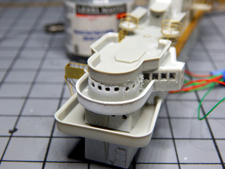
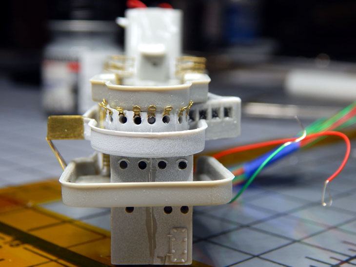
Week 17 on the USS Hornet was more work on the island. I mounted the LED’s in the main part of the island and verified the effect I am looking for worked and it did. I then started working on the catwalks and rails. As I was working on them and checking the photos I noticed the catwalks were grated not solid. I then looked over the many accessories and found that I purchased the White Ensign Models Catwalks Set. I thought it was just the catwalks around the ship but then found out it includes the island catwalks! I then removed the kit catwalks, filled the mounting holes and started mounting the photo etch versions. These look a lot better and appear to be sized correctly. The kit ones looked a little thinner width wise.
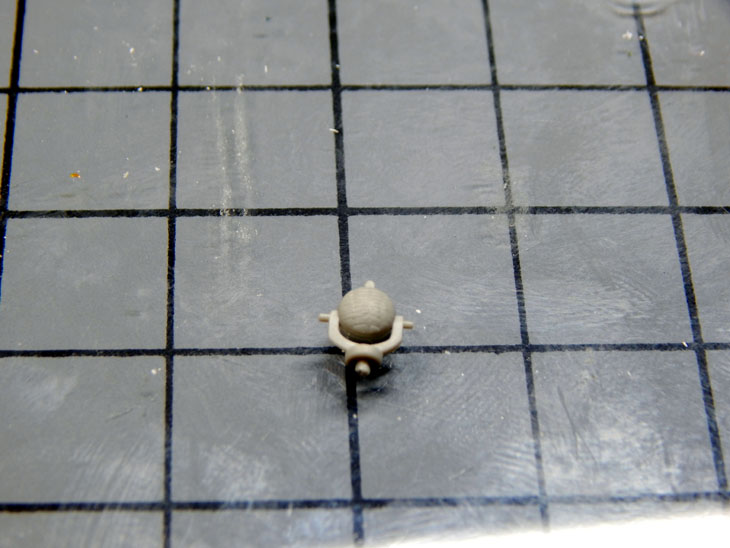
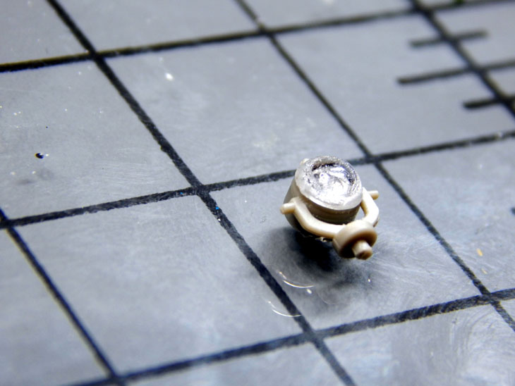
There are two large search lights on each side of the island. These are molded in the kit gray. I decided to make them look more realistic. I took a drill bit the diameter of the search light lens. Drilling into it create a concave divot. This was then painted with chrome silver. I finally covered it with a round clear lens I located in my spare bin.
I then cut off the molded area on the aft side of the island that represents the stairwell. This was replaced with numerous photo etch parts. I am working on the port side island catwalk replacement now then I will work my way up to the masts.
See more photos and details from the start in my build log at https://davidsscalemodels.com/build-log/1-350-uss-hornet-cv-8-doolittle-raid/
-
Thanks All, They have been claimed and will be heading out.
-
Good Morning All,
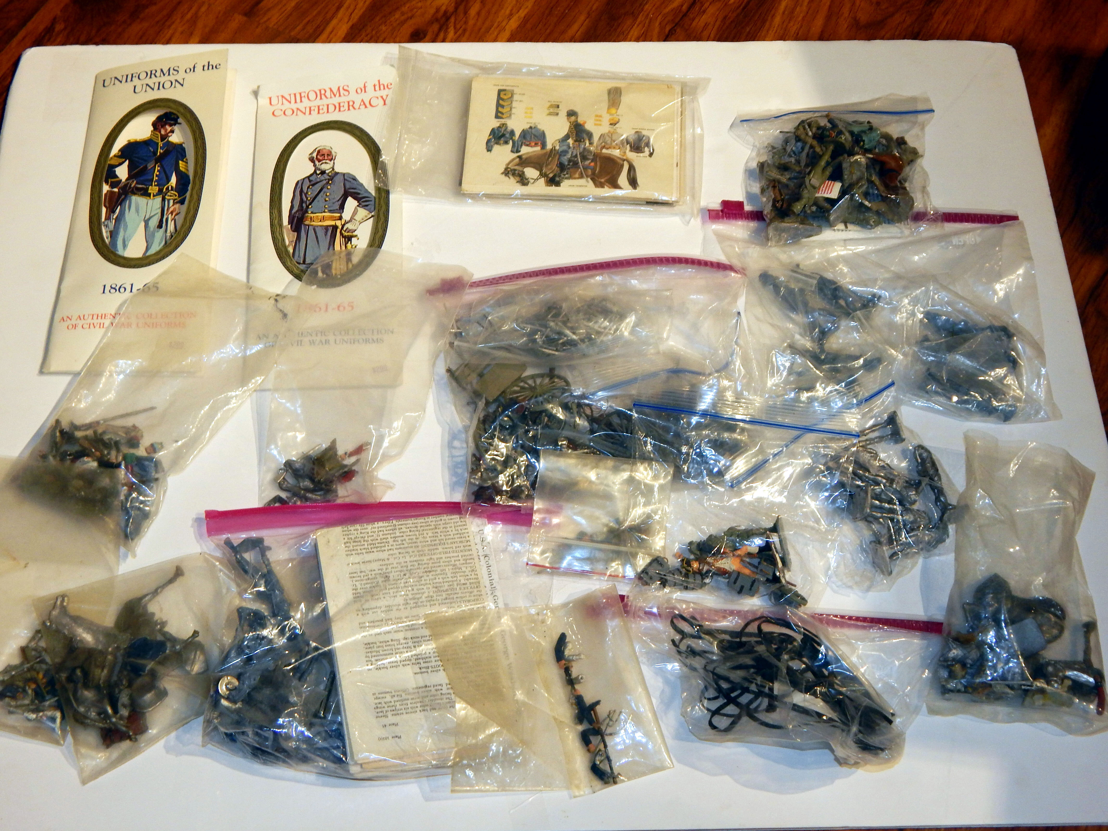
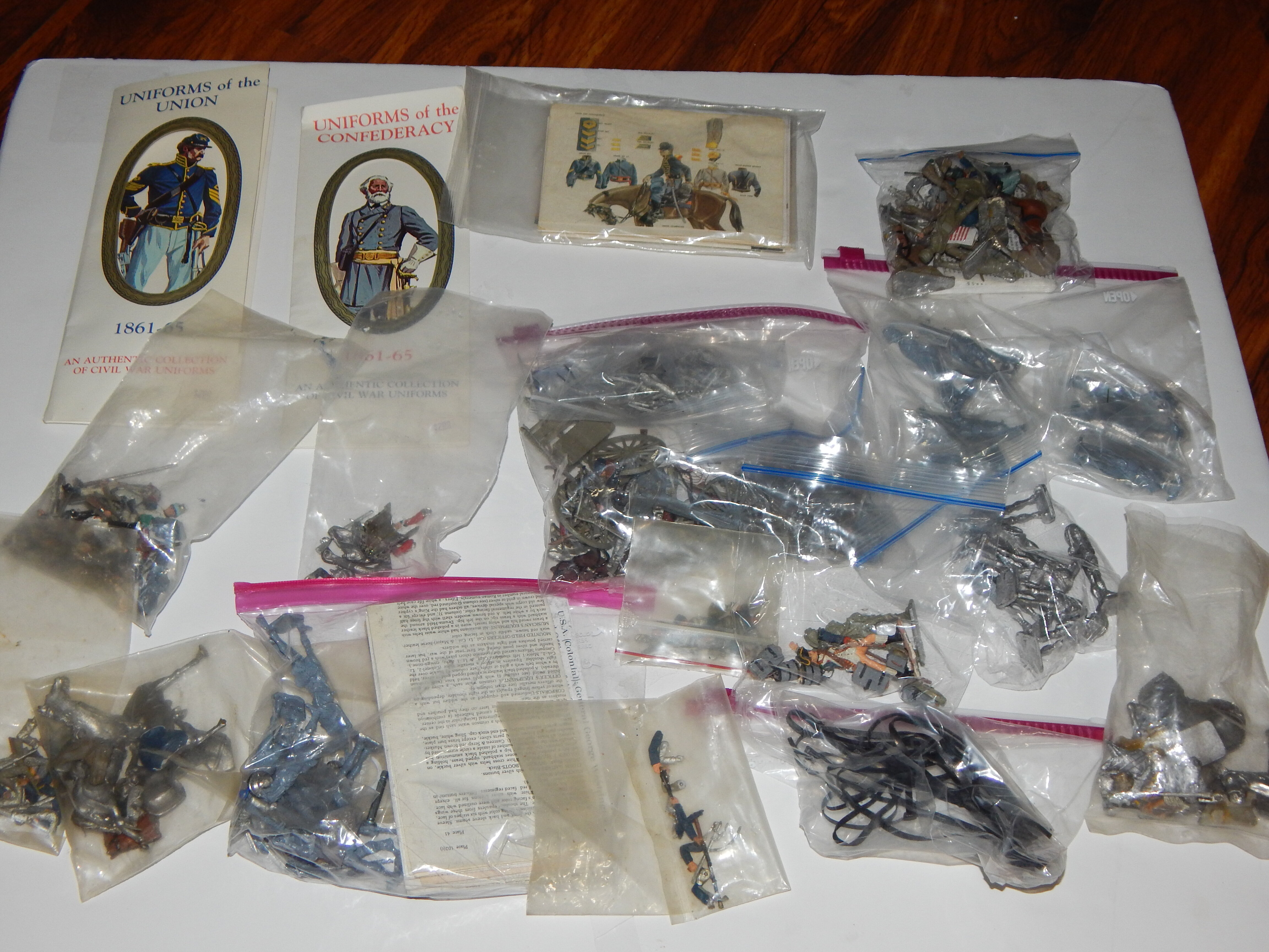
I have a bin full of 1/35 scale civil war figures and accessories. I received these as part of a large box from an estate sale.
I am mostly aircraft and ships. So I am offering the bin (for just shipping costs) to anyone who can use them.
Just PM me.
-
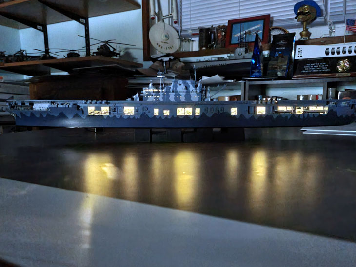
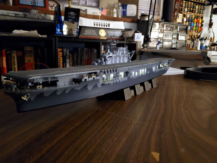
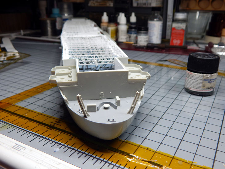
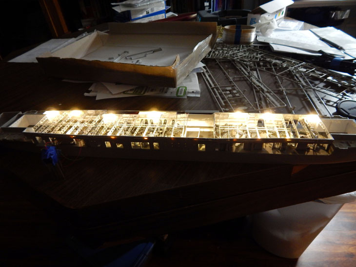
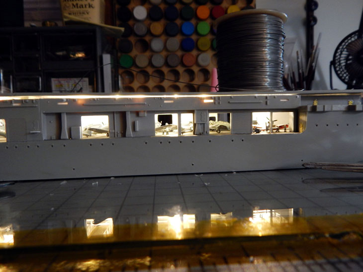
Moving right along for week 16 of the USS Hornet project I have finished installing the hangar deck lights. To get the effect of multiple lights I staggered them from each side. All the wiring was routed to the section under the island so the wiring can be run to the bottom of the hull. With the hangar deck finished I started working on the island.
I first drilled out all the portholes and windows. The windows on the bridge were then filled with acrylic gel to simulate the glass. The bridge is divided into two sections so I used two PICO sized LED’s to light it up. The rest of the island is illuminated with two 5mm LED’s. I then drilled out the funnel caps and replaced them with the photo etch details.
Over the next week I will be detailing the island so I can install it on the flight deck as one assembly. This is needed so I can run the wiring into the hull.
See more photos and details from the start in my build log at https://davidsscalemodels.com/build-log/1-350-uss-hornet-cv-8-doolittle-raid/
-
1
-
-
This is week 15 on the USS Hornet project. I spent most of the week figuring out the light placement and how to route all the wiring. Looks like I will be running a total of 18 LED’s for the hangar deck. For the section between the rear elevator to the mid-ship elevator I have 8 of the NANO size LED’s. These are the “Warm White” color. Placing them on alternate sides and staggering them gives me the best effect. Placing the LED’s is a slow process. I first started by placing the LED into the location and attaching it using acrylic gel. Once the gel is cured I then route the wire and use the gel to hold the in place.
When you look at the photos don’t worry about the girders being bent/warped. Feeding the LED’s and routing the wire causes them to distort as they are handled while feeding the wires and LED’s thru them. I am going to wait until I am ready to install the flight deck before I straighten them. The wires are being routed to the section under the island. Later I will join these with the wiring from the island and run the wires into the bottom of the hull.
Since it takes time for the gel to cure, I stated looking at the island. Since I plan on lighting it as well I drilled out all the port holes and windows on the on it. For the square widow I used a square file. It looks like the bridge has two sections so I will need 2 NANO LED’s. I then need to figure out which LED’s and where to place them inside the main part of the island to give even lighting thru all the port holes. The last of the hangar LED’s are curing now. I then need to do some painting and touch-ups on the wiring to blend them with the hangar deck. Once that is done, I then need to look at the flight deck and prepare it for the wooden flight deck. This will be the first time I will be doing a wooden deck on a model.
See more photos and details from the start in my build log at https://davidsscalemodels.com/build-log/1-350-uss-hornet-cv-8-doolittle-raid/
-
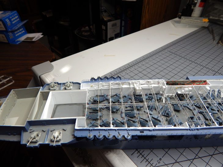
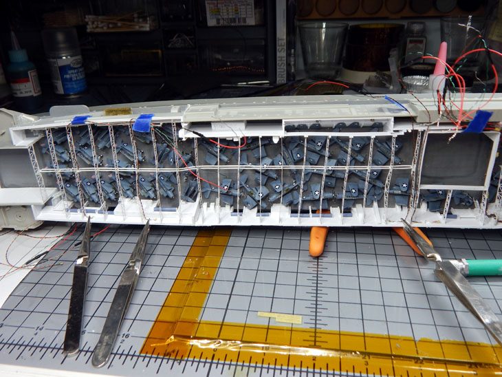
This week on the USS Hornet project I was able to paint many figures and get them placed around the hangar deck. I used mostly the Tamiya figures with a few of the 3-D printed figures. One of the 3-D printed figures was in a seated position so he is now driving a Moto-tug. Another was kneeling so he is working on a dauntless SBD’s dive brakes. The last one I used was one posed walking up a ladder. The rest of the 3-D printed will populate the flight deck and island. With figures placed, I paced all the aircraft back in the hangar and added a few more figures, more moto-tugs, and the weapons carts near the weapons elevator. I then installed the aft girder assembly. This has turned into a slow process. One side needs to be attached and cured before attaching the other side. This is needed to keep the girders straight. I then placed some of the SBD’s in the girders.
With the girders in place I started mapping out where the lighting will go and how to route the wiring for the aft section of the hangar for illumination. I am currently working on the forward section of girders now.
See more photos and details from the start in my build log at https://davidsscalemodels.com/build-log/1-350-uss-hornet-cv-8-doolittle-raid/
-
1
-


1/48 Trumpeter C-47 converted to the R4D-5 “Tropical Tilly”
in Builds
Posted · Edited by Wolfman63
This next build is going to be a little different. I have always been a fan of the 1950’s and 1960’s horror and sci-fi movies. One of my favorites is the Howard Hawks 1951 movie “The Thing From Another World”. The movie is set in the arctic at an outpost that ends up fighting an alien invasion. With that in mind, I will be using the Trumpeter 1/48 C-47 and converting it to a R4D-5 for arctic service. The scheme will be the “Tropical Tilly” used in the movie. For the conversion I will be using Lone Star Models (LSM) arctic C-47 conversion set. The LSM conversion kit includes numerous resin parts for the ski’s, cowls, exhaust, nose, and a set of decals for the Tropical Tilly and another R4D called the Que Sera Sera. For research I took some screen captures from the movie and found some color production stills in an old “Famous Monsters of Filmland” magazine.
Moving on to the start of the build, to begin with I assembled and built the cockpit. One of the things that I noticed was the kit control arms only had 4 thick levers. I cut these off and used some spare photo etch levers. The kit instrument panel is very nice. It consists of a back panel, a thin film with the instrument faces printed on it, and a clear front panel. These went together very well and look great. While I had some painted parts drying I worked on the nose of the aircraft. The R4D nose is a little longer than the normal C-47. The LSM instructions state to cut just forward of the nose panel line and graft the new resin nose on. After some measurements I determined that the nose needed cut 4.0mm forward of the panel line. The resin nose is a near perfect fit now.
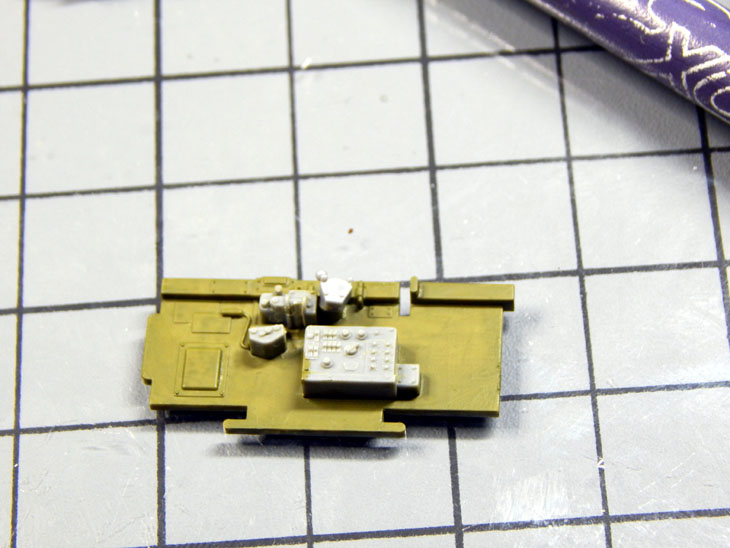
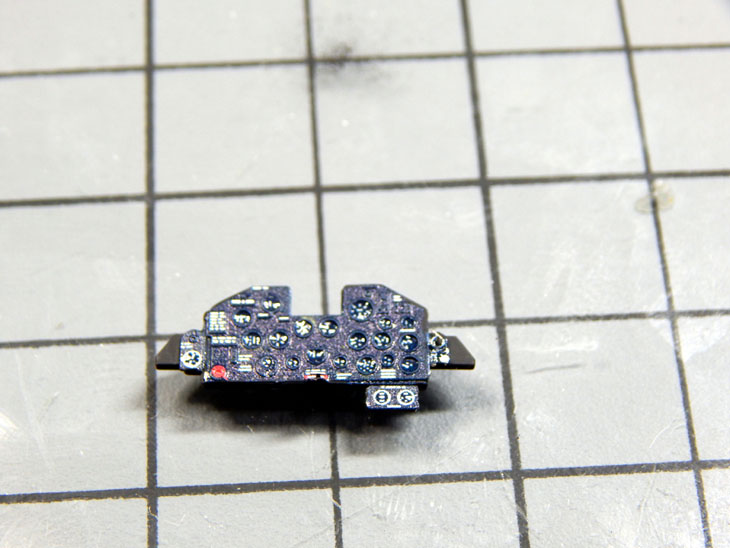
Turning back to the cockpit I built up the seats. The kit provides a small sheet of photo etch that includes the seat belts. After painting them I installed the seat belts and then the control sticks. The next step was to build the avionics rack. The avionics equipment has some details molded on the face. One of the details is the handles of the equipment. I cut these off and replaced them with spare photo etch handles and then detailed the front of all the equipment. I am currently building and detailing the rest of the forward bulkheads.
Check out all the photos and details from start to finish in my build log at https://davidsscalemodels.com/build-log/1-48-r4d-5-tropical-tilly/